

LED Dimming Techniques Using Spread Spectrum Modulation
a technology of spread spectrum modulation and led dimming, which is applied in the direction of electroluminescent light sources, lighting apparatuses, light sources, etc., can solve the problems of complicated circuit components, design and circuit components that cannot be easily controlled,
- Summary
- Abstract
- Description
- Claims
- Application Information
AI Technical Summary
Benefits of technology
Problems solved by technology
Method used
Image

Examples
first embodiment
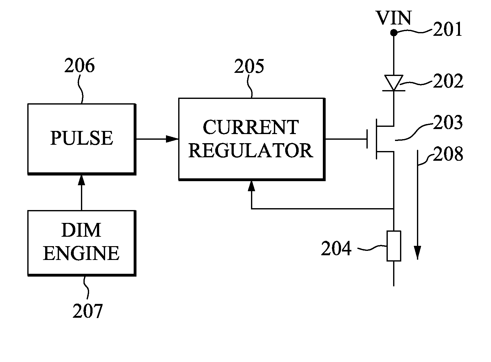
[0033]FIG. 2 conceptually shows a dimming circuit using frequency modulation dimming technique together with a linear LED current regulator, in accordance with the present invention. The figure is for illustrative purpose only and may not show all components which might be known in arts. In FIG. 2, VIN 201 is a current source which generates a periodic current. One end (i.e. anode) of LED(s) 202 is connected to VIN 201 and the other end (i.e. cathode) of LED(s) 202 is connected to the drain of a power device 203 whose gate is regulated by a linear current regulator 205. The current regulator 205 usually includes a gate driver (not shown) which may have an option to be a separate unit. LED(s) 202 can be one LED or many LEDs connected in series or in parallel. Power device 203 can include, but not limited to, a MOSFET, a Bipolar Junction Transistor (BJT) or other device that sources or sinks the LED current. A current sensing resistor 204 is connected between the source of the power d...
second embodiment
[0035]FIG. 3 conceptually shows a dimming circuit using frequency modulation dimming technique and utilizing switching current regulator, in accordance with the present invention. The figure is for illustrative purpose only and may not show all components which might be known in arts. In FIG. 3, VIN 301 is a current source which generates a periodic current. An energy storage element 302, such as an inductor or flyback transformer that is used in common switching regulators, is connected between VIN 301 and one end (i.e. anode) of LED(s) 303. LED(s) 303 can be one LED or many LEDs connected in series or in parallel. The other end (i.e. cathode) of LED(s) 303 is connected to the drain of a power device 304 whose gate is regulated by a switching current regulator 310 comprising a switching controller 309 and a gate driver 308. The switching controller 309 and the gate driver 308 may be integrated as an unit even though they are shown separately in this figure. In alternative embodimen...
third embodiment
[0037]FIG. 4 conceptually shows a dimming circuit using frequency modulation and current bypass method, in accordance with the present invention. The figure is for illustrative purpose only and may not show all components which might be known in arts. In FIG. 4, a current source VIN 401 is connected to a regulated current source 402 which can include either a linear type current regulator or switching type current regulator. When the regulated current source 402 contains a linear type regulator, the regulated current source 402 is equivalent to the combined circuit components of linear regulator 205, power device 203 and current sensing resistor 204 of FIG. 2. On the other hand, when the regulated current source 402 contains a switching type regulator, the regulated current source 402 is equivalent to the combined circuit components of switching regulator 310, power device 304 and current sensing resistor 306 of FIG. 3. The output of the regulated current source 402 goes to both LED...
PUM
 Abstract
Description
Claims
Application Information