Imaging system stand

a technology of imaging system and stand, which is applied in the field of stand, can solve the problems of high effort expenditure, and achieve the effect of improving image captur

Inactive Publication Date: 2012-09-25
SIEMENS HEALTHCARE GMBH
View PDF14 Cites 3 Cited by
  • Summary
  • Abstract
  • Description
  • Claims
  • Application Information

AI Technical Summary

Benefits of technology

[0006]The present embodiments may obviate one or more of the drawbacks or limitations in the related art. For example, in one embodiment, a stand may improve image capture.
[0008]In one embodiment, the counterbalance is provided via a counterweight and enables a user to move a counterbalanced arm effortlessly in space. The counterbalance may be partially overridden temporarily (e.g., for the duration of scanning) when an imaging device must be firmly pressed onto an examination subject, so that the arm automatically presses with at least part of the weight of the arm onto the examination subject (e.g., in the case of mammography, a breast). The user is unburdened and does not press unaided, as in the prior art, on the imaging device with much expenditure of effort. Rather, the counterbalance may be partially overridden so that the stand operates in a quasi “self-acting” manner, and the imaging device is pressed on using the weight of the imaging device or more precisely, a resulting weight force of the arm. The device may move the counterweight automatically against the weight force. Accordingly, the device “lifts” the counterweight so that the weight of the arm, counter-supported via the imaging device already resting on the examination subject, is no longer completely balanced (e.g., the weight of the arm presses the imaging device on the patient using the resulting difference in weight, the difference between the weight of the arm and the “reduced” counterweight). As the arm, in conjunction with the imaging device, has a considerable total weight, a sufficiently high pressing-on force can be generated within the stand, depending on the extent to which the counterbalance is overridden. Accordingly, the user is unburdened, and the pressing-on force remains constant throughout the scanning process. As a result, no appreciable position changes due to unintentional relaxation occur during image capture, because the resulting pressure-exerting weight remains unchanged during the scanning time.
[0013]In one embodiment, the clutch is a friction clutch, which provides a sufficient degree of safety in that the counterbalancing is not excessively or completely overridden, and the arm is not pressed onto the examination subject with excessively high residual force or the entire weight of the arm. The friction clutch may be configured so as to define a maximum torque that can be transmitted from the servomotor via the clutch. If the maximum torque is reached, the clutch will slip so that no further torque transmission, and therefore, no excessively heavy loading of the axis of rotation of the traction roller, becomes possible (e.g., no excessive release to produce an excessively heavy pressure).
[0014]The friction clutch may slip, both in the case of excessive loading via the servomotor and in the case of excessive loading of the axis of rotation of the traction roller via the arm (e.g., the friction clutch may slip in both directions). If the counterbalance is partially overridden via the device, and the examination subject feels the increasing weight of the arm, fear or anxiety may arise, resulting in the examination subject attempting to push the arm up. The arm may be pushed up for reasons of patient safety (e.g., the clutch allows this counter movement). The friction clutch may be configured to slip in both directions to both prevent excessive loading on the part of the servomotor and to allow the patient to actively press against the arm and reduce the pressure.

Problems solved by technology

The user is unburdened and does not press unaided, as in the prior art, on the imaging device with much expenditure of effort.

Method used


Image

  • Imaging system stand
  • Imaging system stand
  • Imaging system stand

Examples


Embodiment Construction

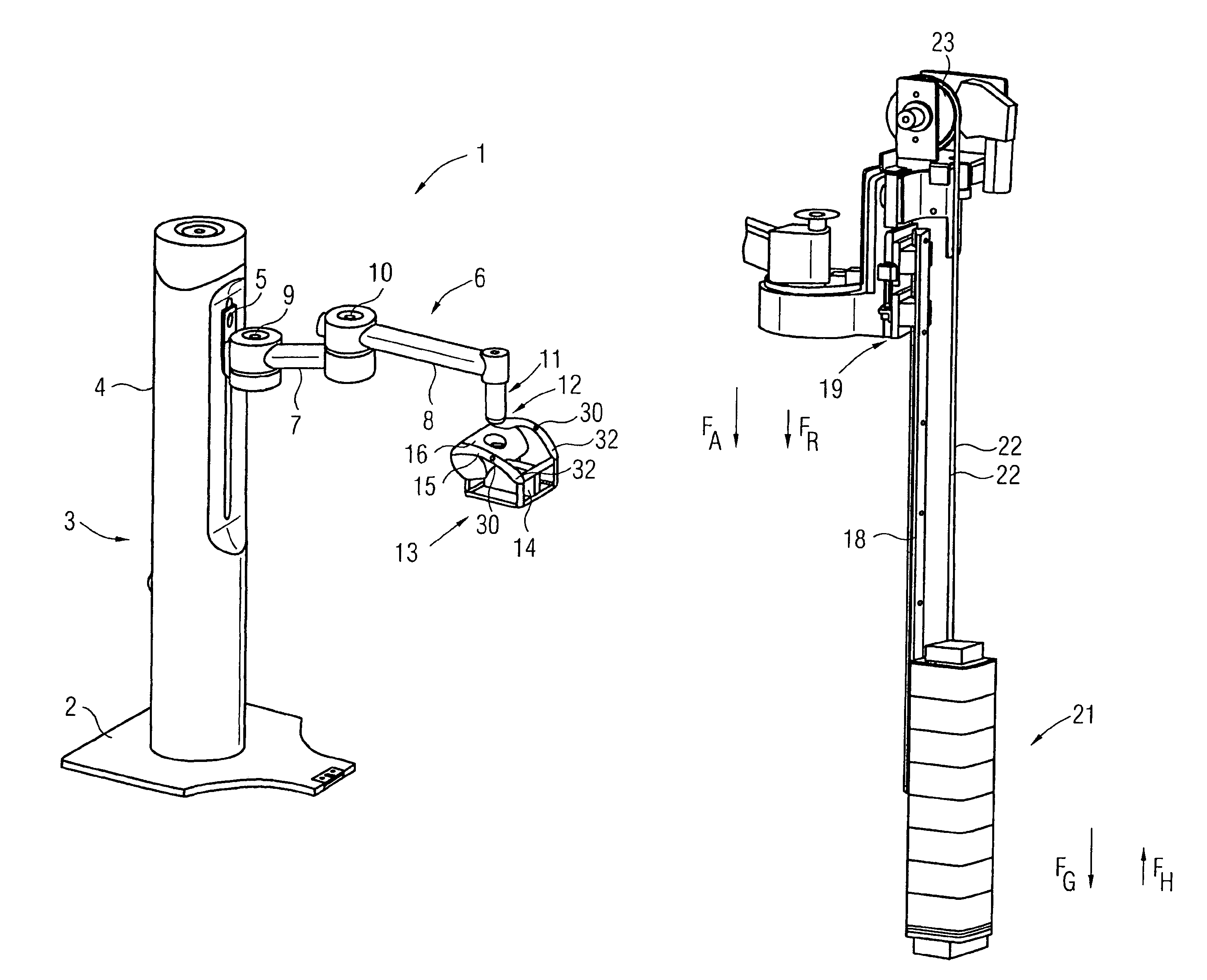
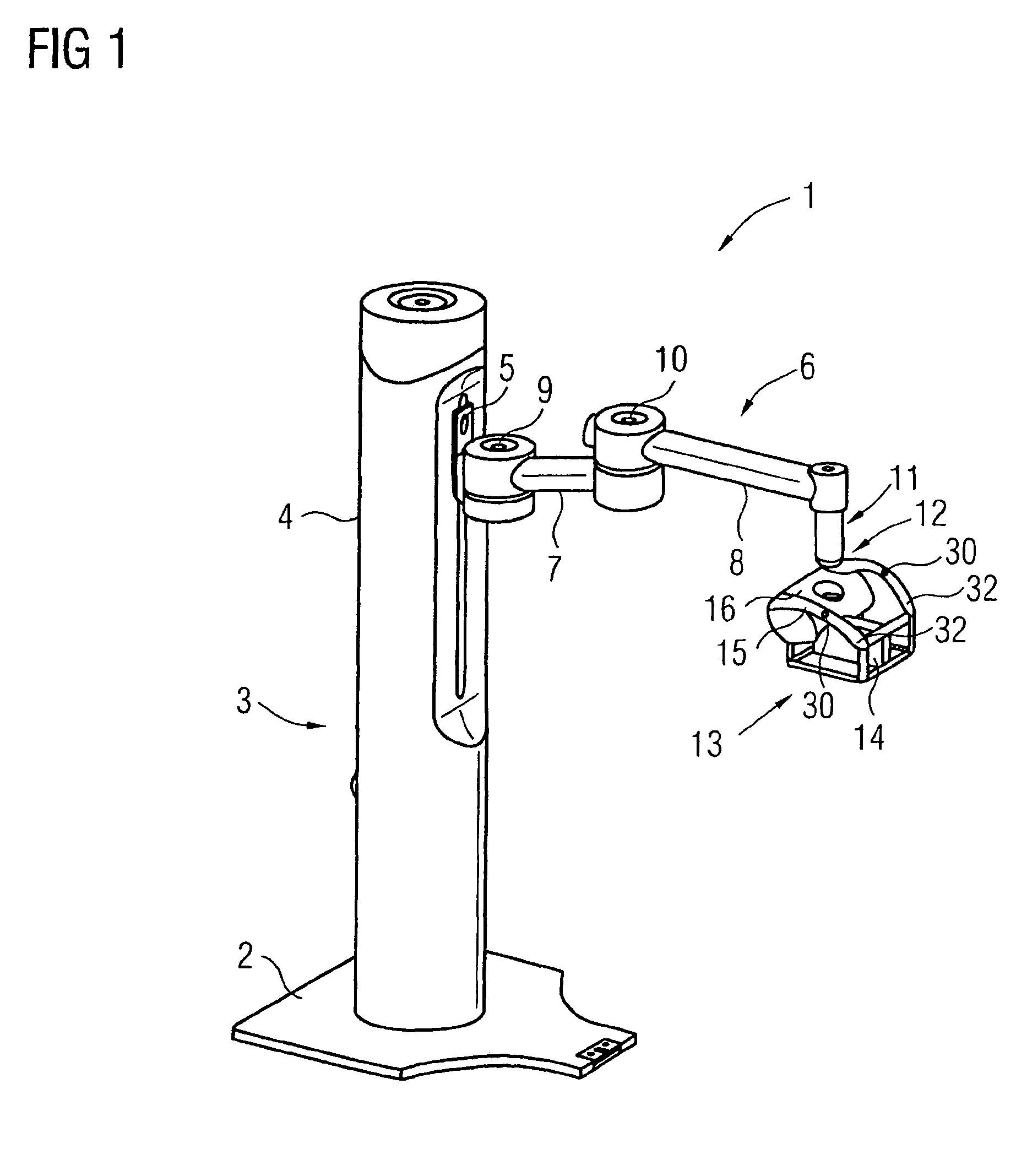
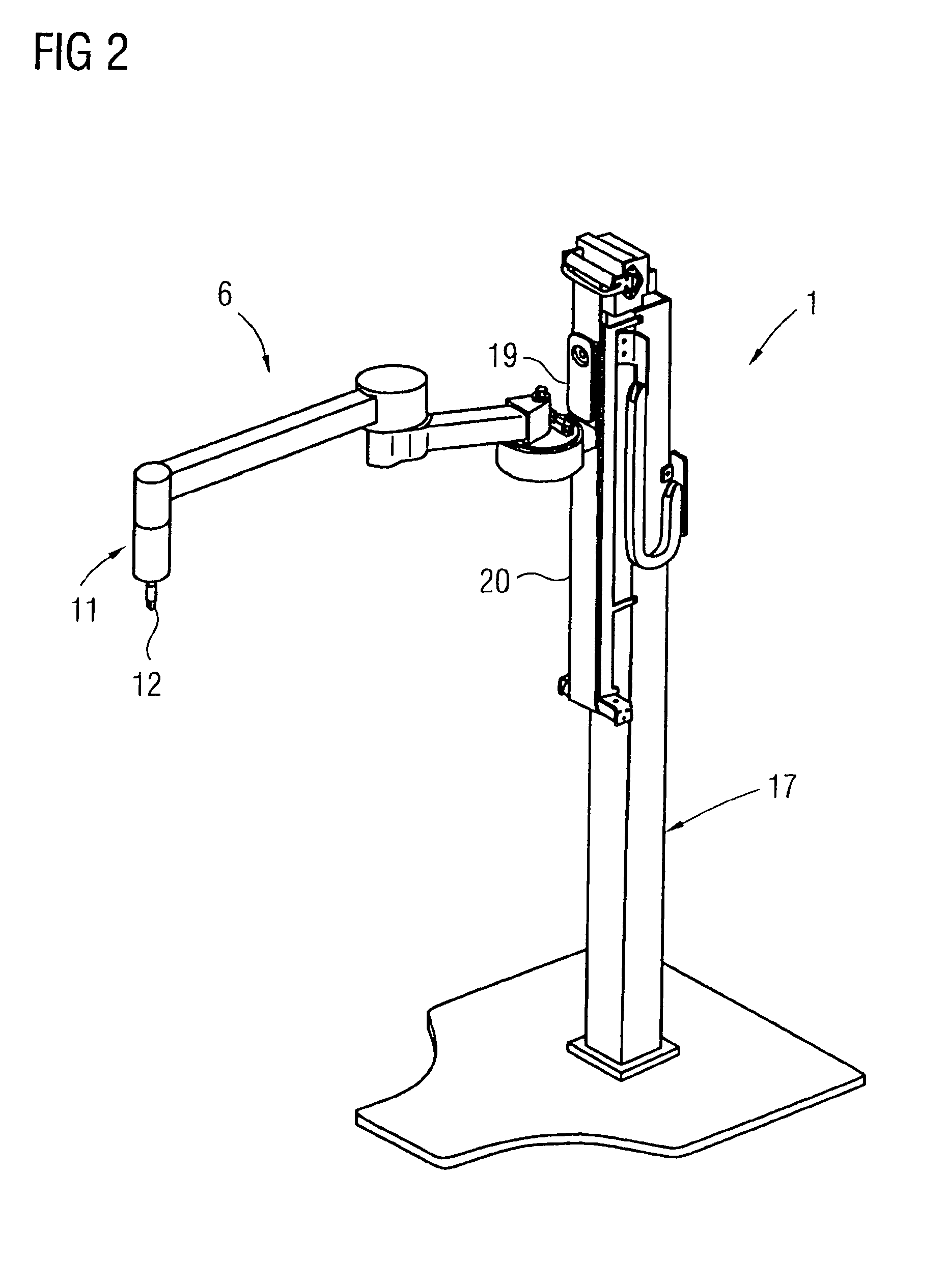
[0023]FIG. 1 shows a stand 1, such as a floor stand, with a base plate 2. A vertical column 3 with paneling 4 is disposed on the base plate 2. Guided vertically on the vertical column 3 is an arm 6 that includes two arm sections 7, 8 and is vertically movable via a linear guide 5. The arm 6 may be swiveled relative to the linear guide 5 via a first pivot joint 9, and a second pivot joint 10 located between the arm sections 7 and 8. The second pivot joint 10 also enables the two arm sections 7 and 8 to swivel relative to one another. On an end of the arm section 8 is an adapter 11 on which an attachment section 12, as shown in FIG. 2, is provided. An imaging device 13 (e.g., an ultrasound transducer 14 for capturing ultrasound images in the context of a mammogram), may be detachably mounted to the attachment section 12. The imaging device 13 may have a frame-like housing 15, on which a section 16 is provided with various operating devices (e.g., a swivel motor, a control device), as ...


PUM


Abstract

A stand, in particular a floor stand, having an arm for holding an object, in particular an imaging device in the form of an ultrasound transducer, said arm being mounted on a vertical column and movable vertically via a vertical guide, wherein a counterweight balancing the weight of the arm is provided on or in the vertical column, a device (24) being provided for moving the counterweight (21) counter to the weight force (FG) for at least partially overriding the counterbalance.

Description

[0001]The present patent document claims the benefit of DE 10 2008 059 331.1 filed Nov. 27, 2008, which is hereby incorporated by reference.BACKGROUND[0002]The present embodiments relate to a stand having an arm for holding an object.[0003]Stands are frequently used with medical imaging devices, such as ultrasound transducers, and have an arm. The arm is coupled to a vertical column in a vertically movable manner. An imaging device, such as an ultrasound transducer is disposed on the arm. Maneuverability of the ultrasound transducer is provided via the maneuverability of the arm and by ball joint mounting the imaging device on the arm. The imaging device may be an ultrasound transducer or a larger device or module, for example having a frame or the like. The imaging device is applied to the patient and positioned by a doctor, for example, to image a breast in the case of a mammogram. The doctor orients the ultrasound transducer according to the position of the breast in order to cor...

Claims


Application Information

Patent Timeline
Patent Type & Authority Patents(United States)
IPC IPC(8): F16M11/00
CPCA61B8/0825A61B8/4218A61B19/26A61B2019/264A61B2019/266A61B90/50A61B2090/504A61B2090/508
Inventor FADLER, FRANZWEIDNER, PAULPANDA, SATCHI
Owner SIEMENS HEALTHCARE GMBH
Why Eureka
Try Eureka