
Article and method for fabricating an applicator tip assembly for a skin formulation applicator

a technology of skin formulation and applicator, which is applied in the field of articles and methods for fabricating applicator tip assemblies, can solve the problems of low durometer silicone parts, large mold cavity size, and difficulty in removing cast parts from fixtures, and achieves the effect of reducing the number of mold cavities, and improving the quality of the finished produ

Active Publication Date: 2012-09-25
LOREAL SA
View PDF28 Cites 12 Cited by
  • Summary
  • Abstract
  • Description
  • Claims
  • Application Information

AI Technical Summary

Benefits of technology

The invention is a casting fixture for making parts that can be used in a skin formulation applicator. The fixture has a part that can be removed easily, called the tear-away section. The fixture is made of a material that doesn't stick to the casting material and can be stored until ready to use. The method involves positioning the base of the applicator in the fixture and adding the casting material. The casting material bonds to the base and can be cured to form a strong connection. This results in a part that can be easily removed from the fixture and used with the applicator.

Problems solved by technology

The casting process can be slow and requires a large quantity of mold cavities, which are generally expensive, in order to meet high volume manufacturing requirements.
In addition, problems may be encountered in removing cast parts from the fixtures, especially low durometer silicone parts.
Further, the silicone parts can often be tacky after they have been removed from the cavity, requiring special handling techniques to ensure that the parts remain clean when they are provided to the user for replacement of existing parts.
Still further, parts comprising low durometer silicone are difficult to attach directly to other elements, such as a drive end of a motor, after they have been cured and otherwise ready for use.

Method used


Image

  • Article and method for fabricating an applicator tip assembly for a skin formulation applicator
  • Article and method for fabricating an applicator tip assembly for a skin formulation applicator
  • Article and method for fabricating an applicator tip assembly for a skin formulation applicator

Examples


Embodiment Construction

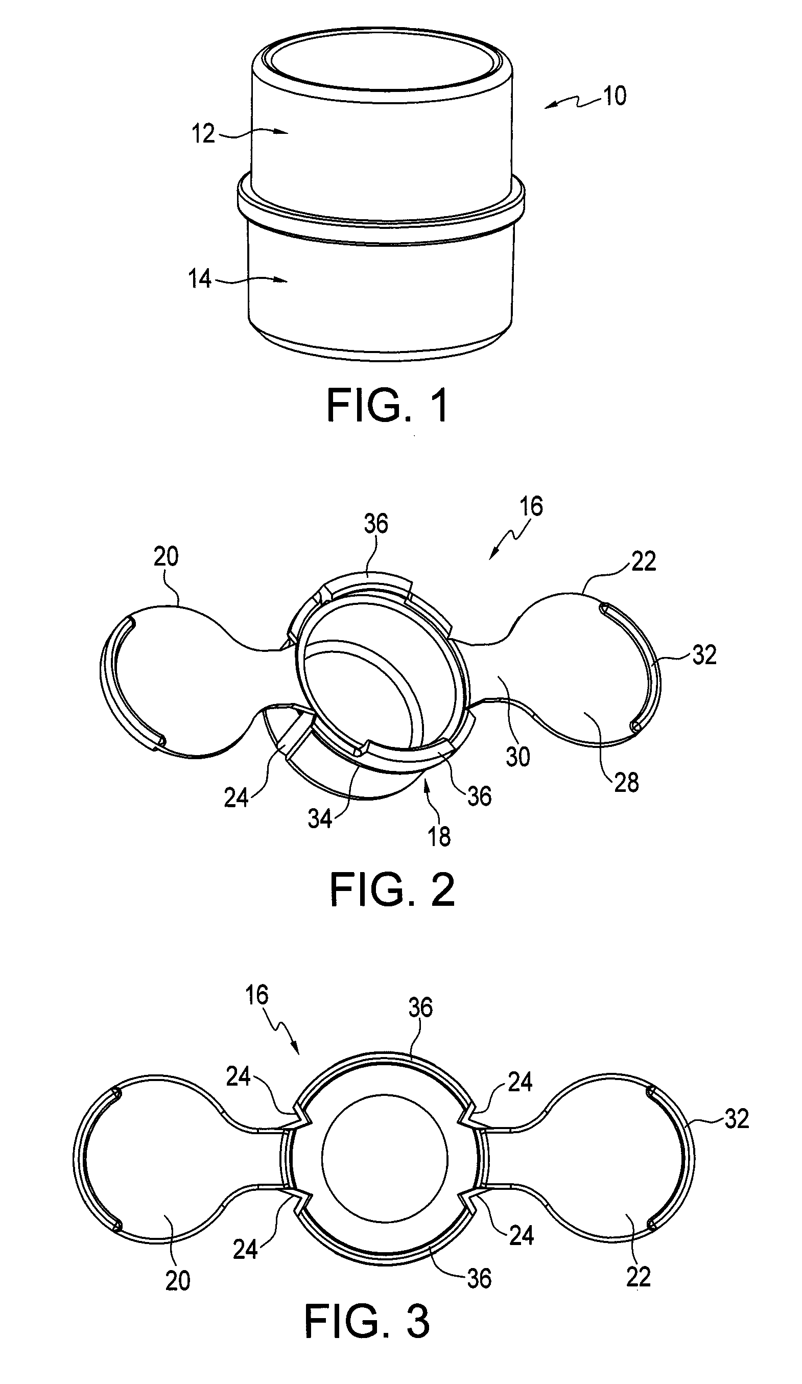
[0012]FIG. 1 shows an example of an appliance part 10 which is fashioned using the casting article and the fabrication method disclosed herein. In this example, part 10 is an applicator tip assembly used in an appliance for applying skin formulations to the facial area of the skin. The applicator tip assembly 10 is described in more detail in co-pending application Ser. No. 12 / 474,426 assigned to the same assignee as the present invention. The information in that application is hereby incorporated by reference.

[0013]Briefly, the applicator tip assembly 10 includes a tip portion 12 which makes physical contact with the user in operation of the applicator. The tip portion 12 must be very soft and, in one example, is approximately Shore scale OO Durometer 30. The applicator tip assembly 10 also includes a base portion 14 which is sufficiently rigid to be conveniently installed and removed from a drive end portion of the applicator motor. As indicated above, there are difficulties using...


PUM

PropertyMeasurementUnit
thickaaaaaaaaaa
thickaaaaaaaaaa
diameteraaaaaaaaaa

Abstract

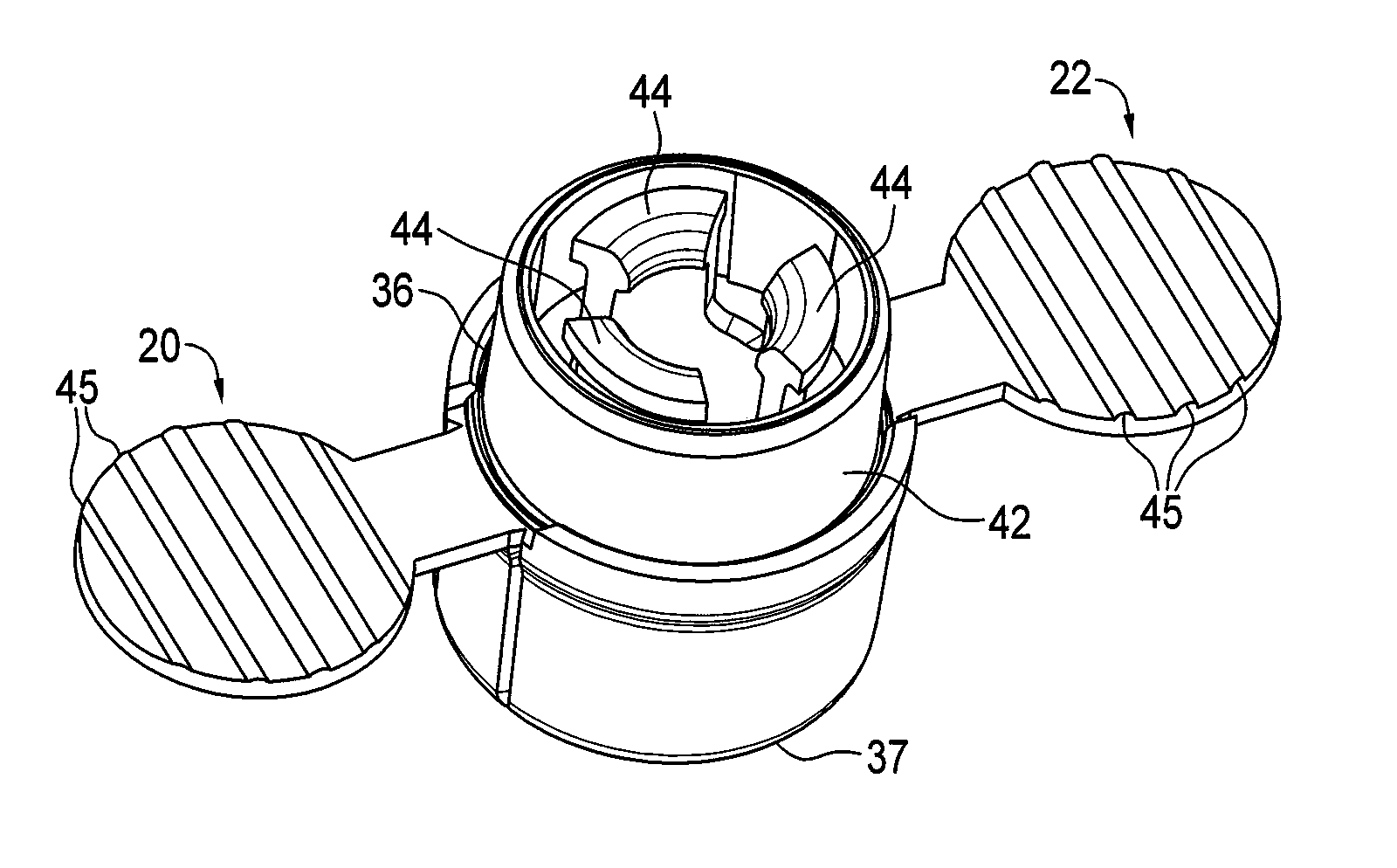
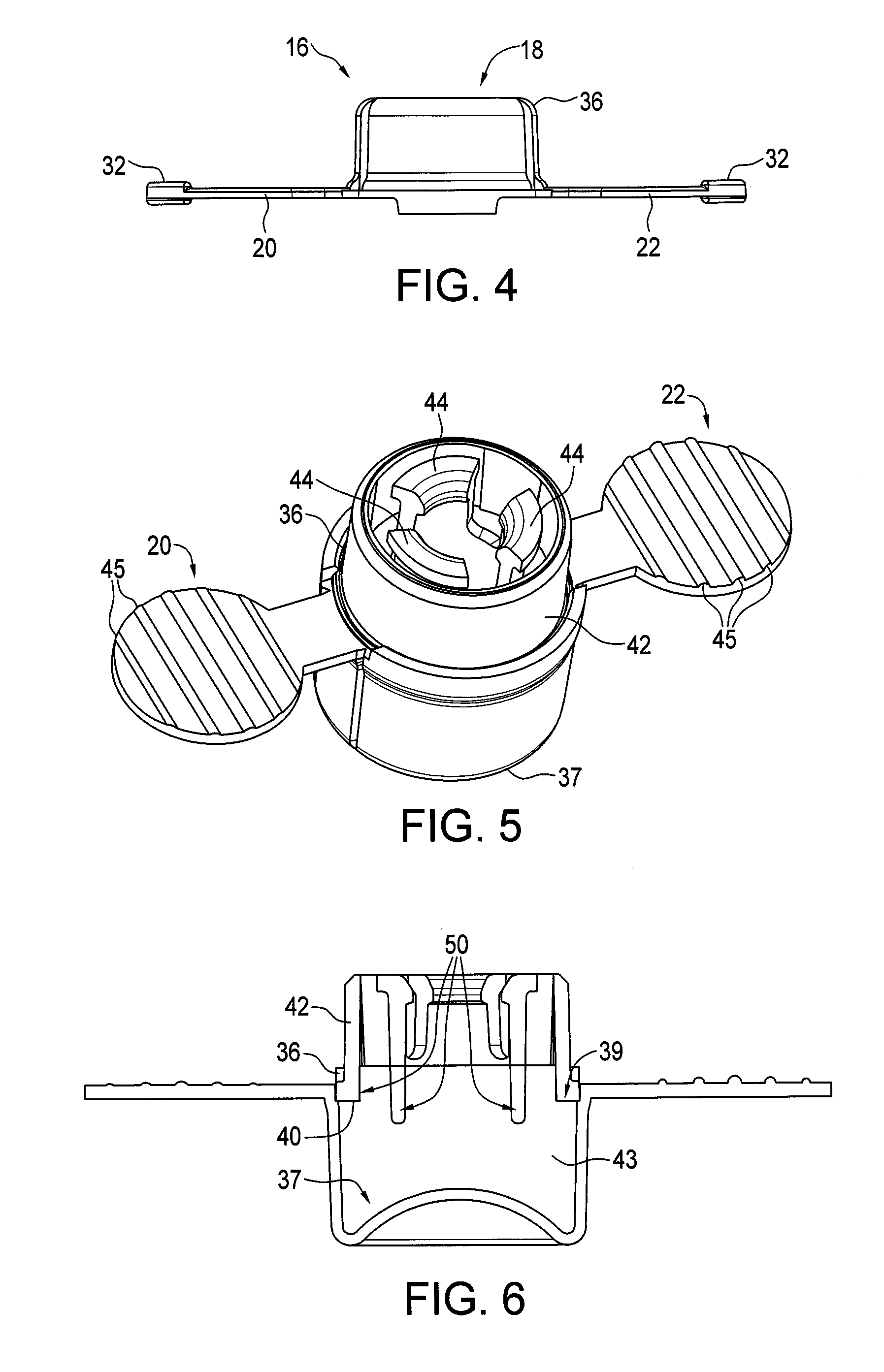
The article and corresponding method include a casting fixture for a part of a skin formulation applicator which is otherwise difficult to cast. The casting fixture includes a central cup section and two opposing tear-away sections. A rigid base portion of an applicator tip assembly is mounted into an upper rim of the cup section and liquid silicone material is poured into the volume defined in the cup section portion beneath the base portion. The silicone cures and bonds to extending elements from the base portion, providing a firm connection between the cast tip portion and the base portion. When the combined part is ready for use, the tear-away sections are removed by the user, which results in an easy ejection of the part, which can then be installed by the user in the formulation applicator.

Description

TECHNICAL FIELD[0001]This invention relates generally to appliances for applying skin treatment formulations to the facial area of the human body, and more particularly concerns an article and method for fabricating an applicator tip assembly used in such an appliance.BACKGROUND OF THE INVENTION[0002]Many parts used in small personal appliances, such as skin formulation applicators, are made by casting methods using a mold / fixture. It is important to control the cost of the cast parts to ensure product success in the marketplace. The cost of the mold and the details of the casting process are both important in controlling costs. The casting process can be slow and requires a large quantity of mold cavities, which are generally expensive, in order to meet high volume manufacturing requirements. In addition, problems may be encountered in removing cast parts from the fixtures, especially low durometer silicone parts. Further, the silicone parts can often be tacky after they have been ...

Claims


Application Information

Patent Timeline
Patent Type & Authority Patents(United States)
IPC IPC(8): B05C19/06
CPCA45D34/04B29C39/10A45D40/0075B29C39/021
Inventor PILCHER, KENNETH AREISHUS, RICHARD AHERLIN, GREGORY W
Owner LOREAL SA
Learn More