Door mounted finger safety device

a finger safety and door technology, applied in the field of door hardware, can solve problems such as commanding a less robust arm structure, and achieve the effect of protecting against injury

Inactive Publication Date: 2012-10-02
RITACHKA ROMAN
View PDF19 Cites 15 Cited by
  • Summary
  • Abstract
  • Description
  • Claims
  • Application Information

AI Technical Summary

Benefits of technology

[0017]The inventive door check device includes an action arm pivotally attached at its proximal end to a base member. The door check base member is configured to be suitably mounted on the door's closing face. The base member may be configured to be mounted to the door through an intermediate wedge or shim element. This results in an angular orientation of the door check action arm relative to the door surface. As the door and the angularly extended action arm are swung toward the doorstop, the door check's angular orientation relative to the closing face of the door results in a substantially normal (right angle) approach to the doorstop. This substantially normal approach minimizes lateral or bending forces on the arm, thus commanding a less robust arm construction. It also lessens scuffing damage to the doorstop.
[0024]Thus, the safety device, in its operative or activated position, prevents full closure of the door leaving a gap at the door's edges which is intended to be at least a predetermined width. Depending upon the intended use of the inventive device, the resultant gap achieved (wider or narrower) can be predetermined or preset by the device's initial placement and configuration. The gap, for example, may be selected at about the thickness of a child's largest finger or the width of a pet's tail.
[0025]While not intended as limiting this invention, an example of a minimal gap between the door and its normally closed position might be in the range of ⅜ inch—generally enough to prevent serious bone injury. This gap may be achieved where the inventive device is mounted near the upper edge of a typical door and spaced about 6 inches from its hinged edge.
[0027]It must be kept in mind that the objective is to afford a relatively narrow gap at the door closure edges, including the hinge-gap located at the door edge opposite the doorknob / latch area. It bears repeating that the gap should be no narrower than a human's finger or other appendages or perhaps the tail, paw or nose of a pet. Gap choices for ventilation, pet passage and such may of course be considerably wider.
[0028]While this description is primarily focused on a child's safety, it will be apparent that the present device may enjoy other applications such as keeping a child from locking himself / herself in a room. As noted, still other uses may include: maintaining a ventilating air flow passage around a door while purposely held slightly ajar. Another application would be to prevent a wind gust from fully closing an open door. A storage trunk may be propped open with this inventive check device in order to aerate its contents. With many storage trunks having metal edges along the closing portions, the present invention can protect against injury. Thus, the invention herein described and claimed as having novel configuration and function should not be considered limited to any specific problem solution.

Problems solved by technology

This substantially normal approach minimizes lateral or bending forces on the arm, thus commanding a less robust arm construction.

Method used


Image

  • Door mounted finger safety device
  • Door mounted finger safety device
  • Door mounted finger safety device

Examples


Embodiment Construction

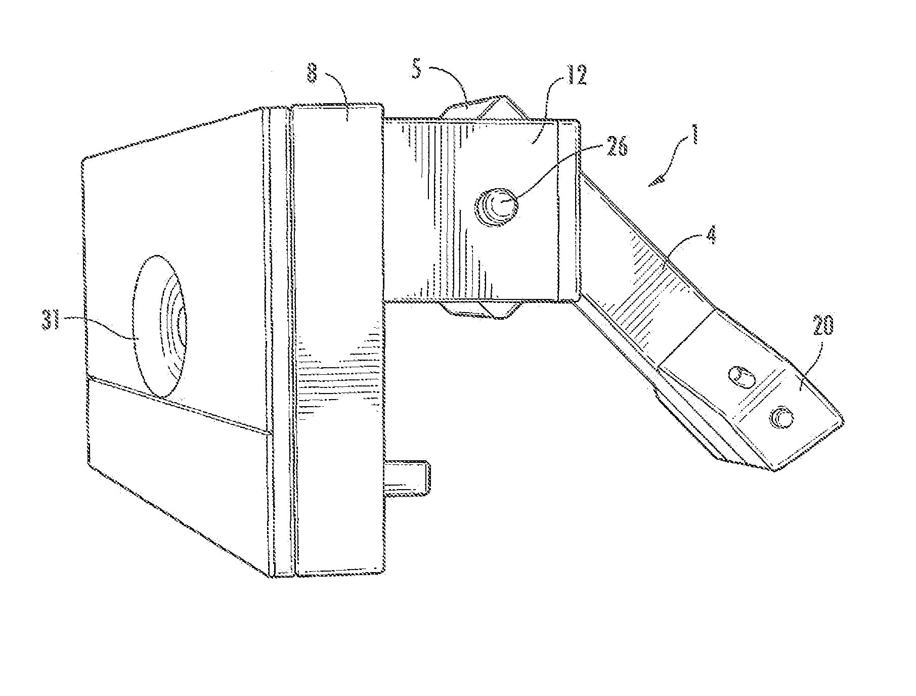
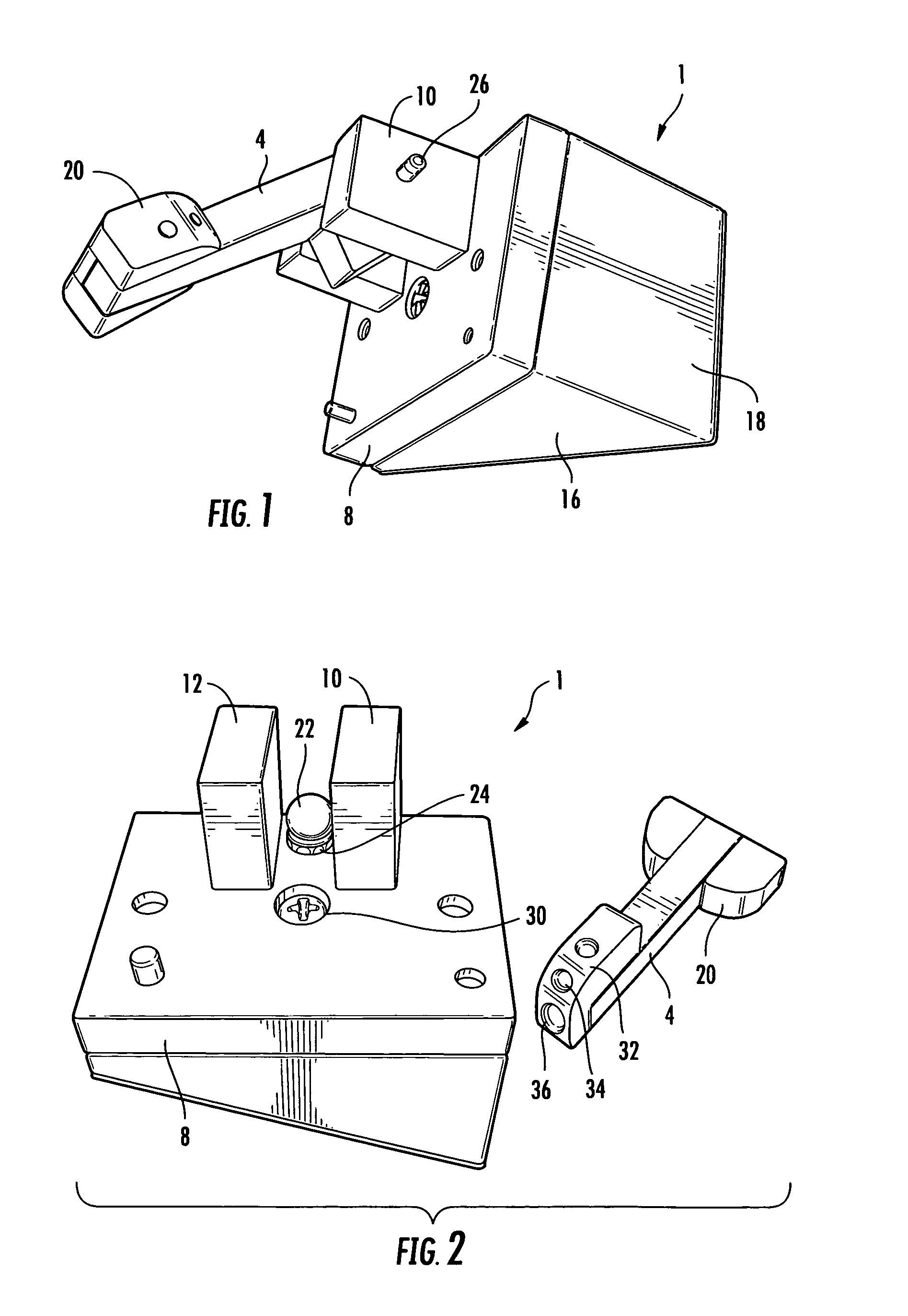
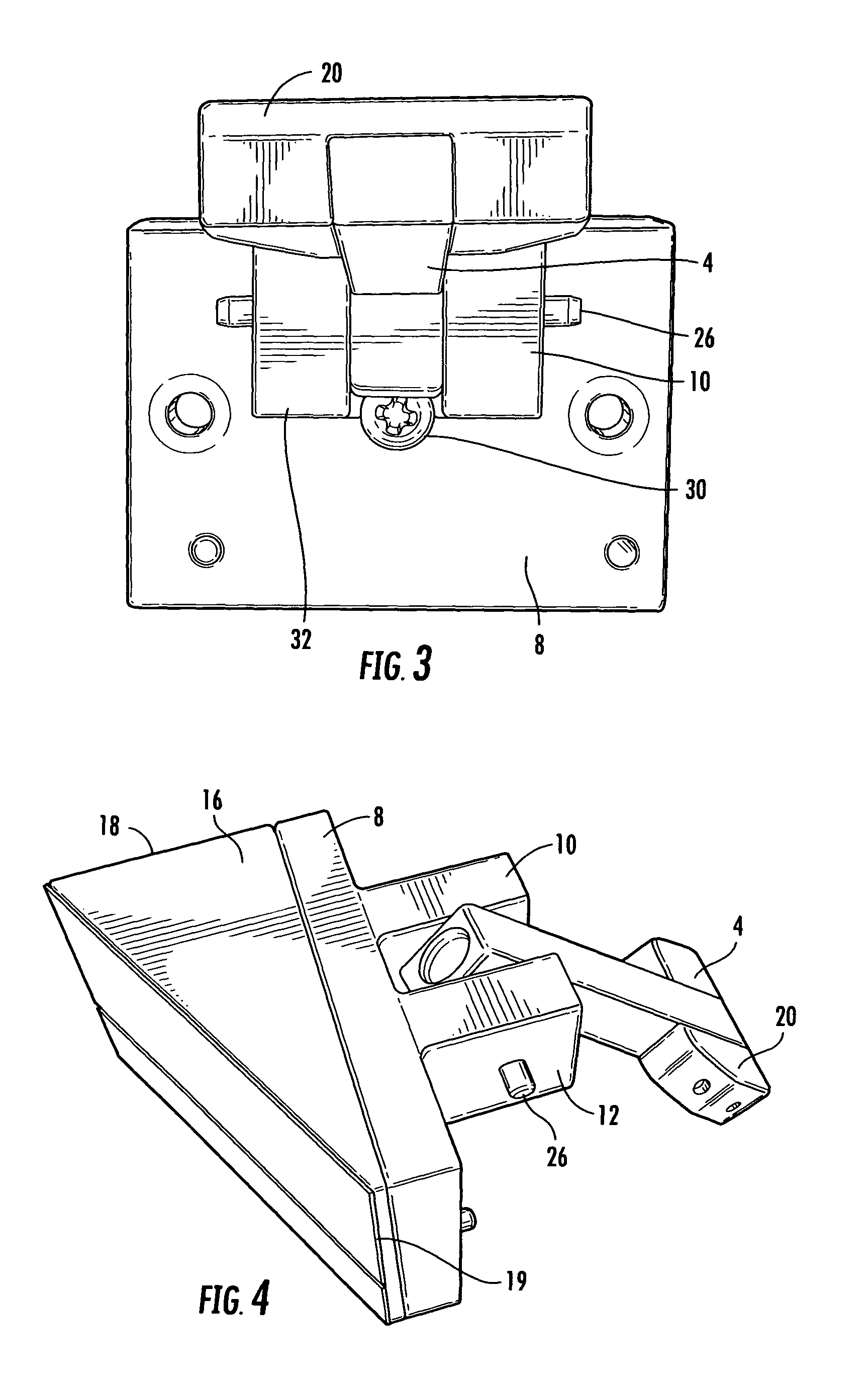
[0042]Looking more closely at the inventive door check device 1 depicted in FIGS. 1-12, it will be seen that the principal operative element is the outwardly projecting, articulated impact or action arm 4. This action arm 4 and its associated components may be fabricated from any of a variety of source materials. These materials include but are not limited to plastic, wood, metal, and the like, bearing in mind that to be qualified a source material must be sufficiently substantial to withstand repeated compressive and shearing impacts. Since this inventive device 1 is intended for widespread use, it also is important that the selected source materials be relatively inexpensive and easily manufactured and assembled.

[0043]The door check device 1 with impact or action arm 4 as viewed in FIGS. 1 and 2 extends from a proximal end at a base 8 to which it is mounted on pivot pin 26 in journal bearing block elements 10 and 12 (integral with, or affixed to, the base 8). The action arm extend...


PUM


Abstract

A door check device to be mounted to a door for selectively maintaining a gap when door closing is attempted. This prevents injuries to children's fingers and the like. The door check includes a base with a journal having action arm pivoted at its proximal end. The arm has a distal end extending outwardly to engage a doorstop. Indexing sockets are formed along the arm's proximal end. Each socket collaborates with the nose of a spring-biased detent to retain the action arm in a preselected position. The arm may be set in a first position to directly engage the doorstop to form a gap. Set in a second position the arm allows door closing but, upon next opening, the arm automatically reverts to door checking position. In a third position the arm is fully lowered to disable the check device. This device may find application to a variety of closures.

Description

REFERENCE TO RELATED APPLICATIONS[0001]This application is entitled to the benefit of provisional patent application Ser. No. 61 / 136,404 filed Sep. 3, 2008; such benefit is hereby claimed under 35 USC 119(e) and the content of said application in its entirety and for all purposes is incorporated herein by reference.STATEMENT REGARDING FEDERALLY SPONSORED RESEARCH OR DEVELOPMENT[0002]Not applicableREFERENCE TO SEQUENCE LISTING[0003]Not applicableBACKGROUND OF THE INVENTION[0004]1. Field of the Invention[0005]The invention disclosed herein generally relates to the field of door hardware and more specifically to mechanisms for preventing a door or equivalent closure from fully closing by mechanically maintaining at least a small gap along each lateral edge, thereby keeping the door slightly ajar. Described herein are a unique gap-retaining mechanism and its method of use.[0006]Each year, tens of thousands of children in the United States receive serious injuries when closures accidenta...

Claims


Application Information

Patent Timeline
Patent Type & Authority Patents(United States)
IPC IPC(8): E05F5/04
CPCE05F5/02E05F5/04E05F5/06E05Y2800/41Y10T16/615Y10T16/6285Y10T16/61Y10T16/625Y10T16/629E05Y2900/132Y10T292/71Y10T292/73
Inventor RITACHKA, ROMAN
Owner RITACHKA ROMAN
Why Eureka
Try Eureka