Curtain

a curtain cloth or shade technology, applied in the field of curtains, can solve the problems of inability to rotate the shaft in reverse, the rotary shaft is in a free state, etc., and achieve the effect of reducing the free falling speed of the curtain cloth or shade, avoiding adverse influence on the entire device, and enhancing the frictional speed reducing

Inactive Publication Date: 2012-10-09
ZHU XIANGRONG
View PDF22 Cites 24 Cited by
  • Summary
  • Abstract
  • Description
  • Claims
  • Application Information

AI Technical Summary

Benefits of technology

[0003]It is an object of the present invention to provide a curtain that can be used safely and conveniently. The curtain has a pull rope rotary disc capable of concealing a relatively long section of pull rope to avoid exposure of an excessive rope section such that reverse rotation of the curtain reeling drum will not be adversely affected by the pull rope drive mechanism.
[0006]The pressure spring is mounted between the rotary shaft and the clutch sliding rotary head. The pressure spring assures the slider to push the clutch sliding rotary head to move away from the rotary shaft with the end face of the clutch sliding rotary head disengaged from the rotary shaft under the action of the pressure spring when the slider is reversely moved along the inclined slot, to enable the rotary shaft to be in a free state and smoothly rotate with the curtain reeling drum.
[0009]In order to reduce the free falling speed of the curtain cloth or shade to thereby avoid adverse influence upon the entire device, the curtain bracket is provided with a speed reducing device connected to the transmission shaft. The speed reducing device is comprised of a box body, a speed shifting mechanism mounted in the box body and connected to the transmission shaft, and a frictional speed reducing mechanism driven by the speed shifting mechanism. The speed shifting mechanism is comprised of a gear or a gear train, and a worm engaged with the gear or an output gear of the gear train. Output shafts of the worm are mounted in the box body via bearings. One of the output shafts of the worm is connected to the frictional speed reducing mechanism. The frictional speed reducing mechanism is comprised of a rotary base, a friction block swingingly connected to the rotary base, and a circular chamber formed in the box body. The friction block is positioned in the circular chamber. In order to enhance the frictional speed reducing effect, the output shafts at both ends of the worm are connected to the frictional speed reducing mechanism. The bearing is a steel ball mounted between an axial hole and the output shaft on the worm.
[0011]In comparison with the prior art, the present invention has advantages of safety and convenience as well as the use with various kinds of curtain cloths or shades without exposure of an excessive pull rope section.

Problems solved by technology

Thus, the rotary shaft is in a free state and cannot be rotated reversely under the action of the reverse rotation releasing device.

Method used


Image

  • Curtain
  • Curtain
  • Curtain

Examples


embodiment 1

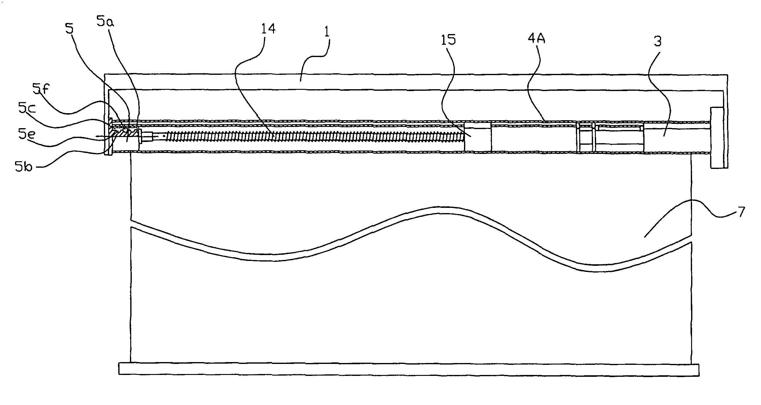
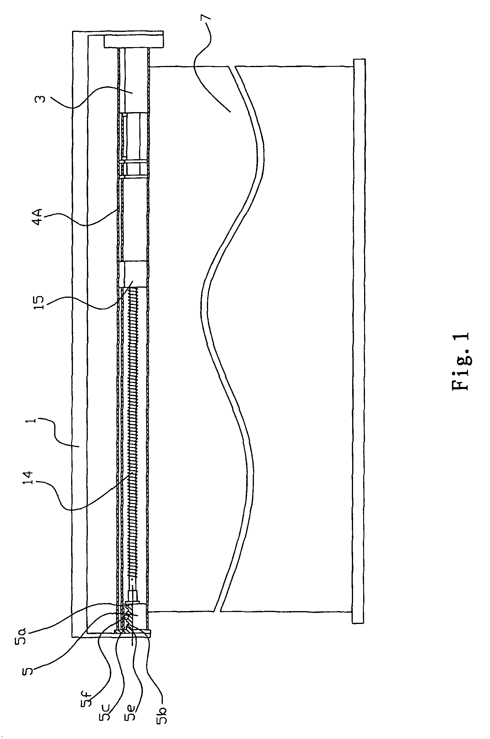
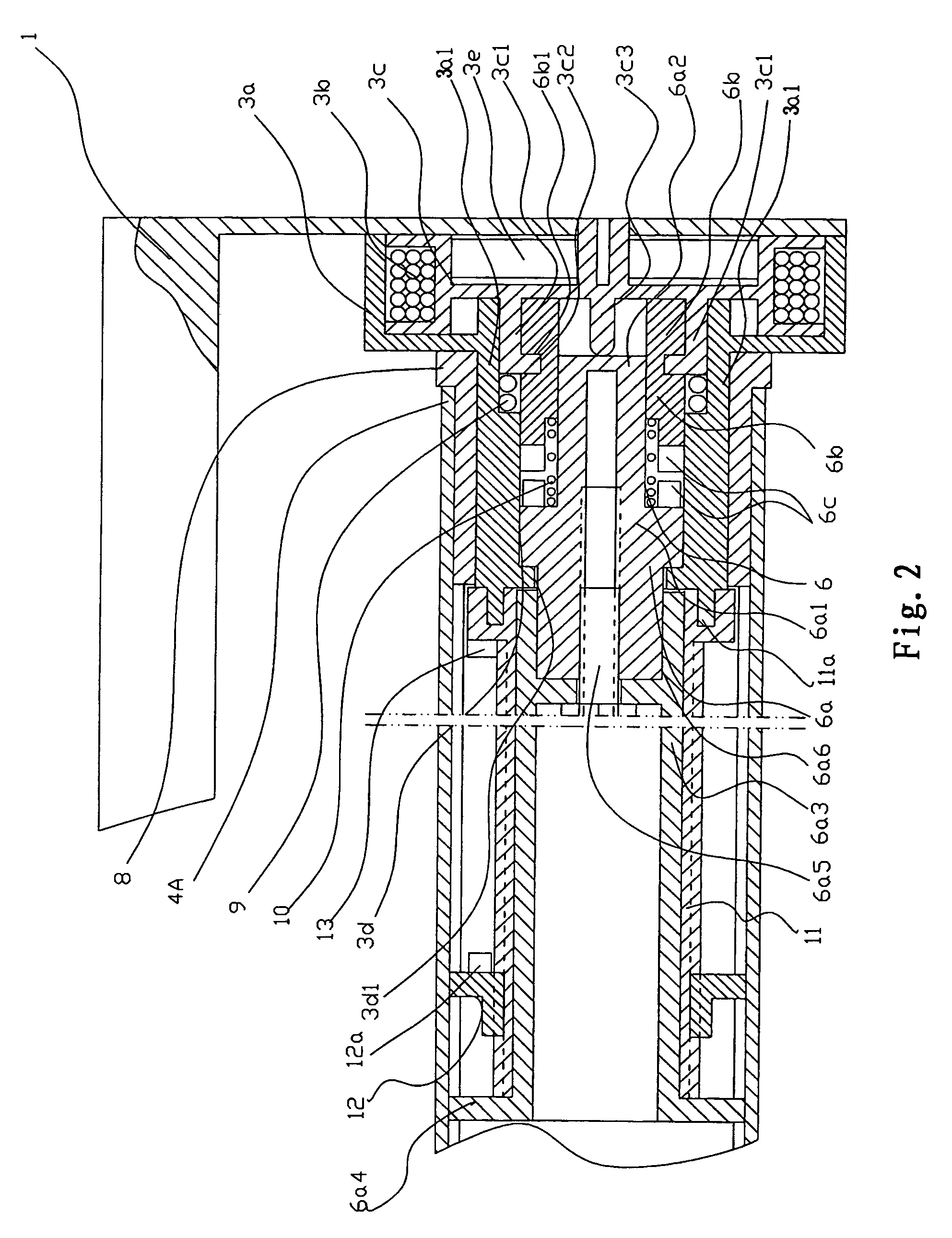
[0028]The curtain of the present invention is comprised of a curtain bracket 1, a rotation driving device 3 mounted to an end of the curtain bracket 1, a curtain reeling drum 4A driven by the rotation driving device 3, a curtain cloth 7 driven by the curtain reeling drum 4A, a reverse rotation releasing device 5 connected to the rotation driving device 3, and a resilience reverse rotation mechanism 14, as shown in FIGS. 1, 2, and 7. The rotation driving device 3 is comprised of a pull rope rotary disc box 3a fixed on the curtain bracket 1, a pull rope rotary disc 3c rotatably mounted in the pull rope rotary disc box 3a and wound with a pull rope 3b, and a unidirectional clutch device 6 connected to the pull rope rotary disc 3c. A rewinding spring 3e is mounted between the pull rope rotary disc 3c and the curtain bracket 1. The curtain reeling drum 4A is rotatably mounted to a reeling drum shaft 3a1 of the pull rope rotary disc box 3a by a reeling jacket tube 8. The unidirectional cl...

embodiment 2

[0036]The present invention is comprised of a curtain bracket 1, a rotation driving device 3 mounted to an end of the curtain bracket 1, a curtain reeling drum 4A driven by the rotation driving device 3, a curtain cloth 7 driven by the curtain reeling drum 4A, and a reverse rotation releasing device 5 connected to the rotation driving device 3, as shown in FIG. 12 and FIG. 7. The rotation driving device 3 is the same as the rotation driving device 3 used in the first embodiment, as shown in FIG. 12.

[0037]The reverse rotation releasing device 5 is comprised of a sleeve 5a connected to the curtain reeling drum 4A, and a sleeve shaft 5b mounted in the sleeve 5a and fixed to the curtain bracket 1. As shown in FIG. 8, an interior side wall of the sleeve 5a is provided with a guide groove 5c. A continuous sliding path 5e is formed along a surface 5d of the sleeve shaft 5b. A ball 5f is mounted between the guide groove 5c and the sliding path 5e. The sliding path 5e is comprised of one or ...

embodiment 3

[0043]The present invention is comprised of a curtain bracket 1 with a rope reeling guide groove 1a, a rotation driving device 3 mounted on the curtain bracket 1, a plurality of reeling rope devices 4 mounted on the curtain bracket 1 and driven by the rotation driving device 3, a curtain cloth or shade 7 driven by the reeling rope devices 4, and a reverse rotation releasing device 5 connected to the rotation driving device 3, as shown in FIGS. 3, 4, and 7. The rotation driving device 3 is comprised of a pull rope (pull tape) rotary disc box 3a secured to the curtain bracket 1, a pull rope rotary disc 3c rotatably mounted in the pull rope (pull tape) rotary box 3a and wound with a pull rope (pull stripe) 3b, and a unidirectional clutch device 6 connected to the pull rope rotary disc 3c. A rewinding spring 3e is mounted between the pull rope rotary disc 3c and the pull rope rotary disc box 3a. A cover 3f is fixed by a screw to an opening of the pull rope rotary disc box 3a to position...


PUM


Abstract

A curtain includes a curtain bracket (1) having an end to which a rotation driving device (3) is mounted. The rotation driving device (3) can actuate a curtain reeling drum (4A) to rotate a curtain cloth (7) or actuate a reeling rope device (4) to rotate a curtain cloth or shade (7). A reverse rotation releasing device (5) and a resilience reverse rotation mechanism (14) are connected to the rotation driving device (3). The rotation driving device (3) is comprised of a pull rope rotary disc (3c), a unidirectional clutch device (6) connected to the pull rope rotary disc (3c), and a rewinding spring (3e) mounted between the pull rope rotary disc (3c) and a pull rope rotary disc box (3a). Thus, only one cord is sufficient to control opening of the curtain cloth or shade (7), and reverse rotation of the curtain reel drum (4A) is not adversely affected by the rotation driving device (3). It is convenient to use while avoiding injury to children.

Description

FIELD OF THE INVENTION[0001]The present invention relates to a curtain.BACKGROUND OF THE INVENTION[0002]Curtains in the prior art that move a curtain cloth or shade vertically by a reeling rope or a reeling drum are generally comprised of a curtain bracket, a rotation driving device mounted on the curtain bracket, and a reeling rope device or a reeling drum mounted on the curtain bracket and driven by the rotation driving device. Some of the curtains are further provided with a speed reducing device to prevent the transmission members from being damaged as a result of a rapid fall of the curtain cloth or shade. The rotation driving device of the curtains is operated either by an endless bead chain (pull rope) or by a pull rope wound inside the reeling drum to wind or release the curtain. However, when it is manipulated by the endless bead chain (pull rope), a U-shaped rope loop will be formed by the hanging endless bead chain (pull rope), and a child playing around may be strangled ...

Claims


Application Information

Patent Timeline
Patent Type & Authority Patents(United States)
IPC IPC(8): A47G5/02
CPCE06B9/42E06B9/56E06B9/68A47G5/02E06B7/086
Inventor ZHU, XIANGRONG
Owner ZHU XIANGRONG
Why Eureka
Try Eureka