Oil filter assembly and associated filter element

a technology of oil filter and filter element, which is applied in the direction of filtration separation, machine/engine, separation process, etc., can solve the problems of supporting tube clogging, and achieve the effect of simple construction, reduced intrinsic rigidity in the axial direction, and high intrinsic rigidity

Active Publication Date: 2012-10-09
MANN HUMMEL GMBH
View PDF8 Cites 1 Cited by
  • Summary
  • Abstract
  • Description
  • Claims
  • Application Information

AI Technical Summary

Benefits of technology

[0013]The cover element may also have a supporting tube abutment area on its side facing the receiving chamber such that, when the filter element is disposed on the supporting tube, the supporting tube is directly loaded by the supporting tube abutment area and displaced into the operating position when the receiving chamber is being closed. In contrast to prior art, the supporting tube is consequently immediately brought into the operating position directly by the cover element, via its supporting tube abutment area, when the cover is being closed. The supporting tube is thereby displaced into the operating position directly via the cover element that acts against the supporting tube and not via the filter element. This is advantageous in that the filter element itself does not need to have a high intrinsic rigidity and may therefore have a relatively simple construction. In particular, the filter element does not require any components that transmit forces in the axial direction. Prior art devices have shown that, when filter elements are used on a long-term basis, their intrinsic rigidity in the axial direction can decrease, which could cause the supporting tube to be unintentionally displaced into the drain position. In accordance with the invention, it is therefore decisive that the filter element does not retain the supporting tube in its operating position.
[0014]The cover element may moreover have a supporting tube abutment area on its side facing the receiving chamber such that, when the filter element is disposed on the supporting tube and the receiving chamber is closed, the supporting tube abutment area directly keeps the supporting tube in the operating position. The supporting tube abutment area consequently keeps the supporting tube in its operating position during operation of the oil filter assembly. This is also advantageous in that, during operation of the oil filter assembly, the filter element does not have to transmit any axial forces in order to keep the supporting tube in the operating position. In this respect, the construction of the filter element is facilitated compared to conventional oil filter assemblies.

Problems solved by technology

Its has turned out that, after long-term operation of oil filter assemblies, the supporting tube clogs, in particular, in the area where it closes the drain opening.

Method used


Image

  • Oil filter assembly and associated filter element
  • Oil filter assembly and associated filter element
  • Oil filter assembly and associated filter element

Examples


Embodiment Construction

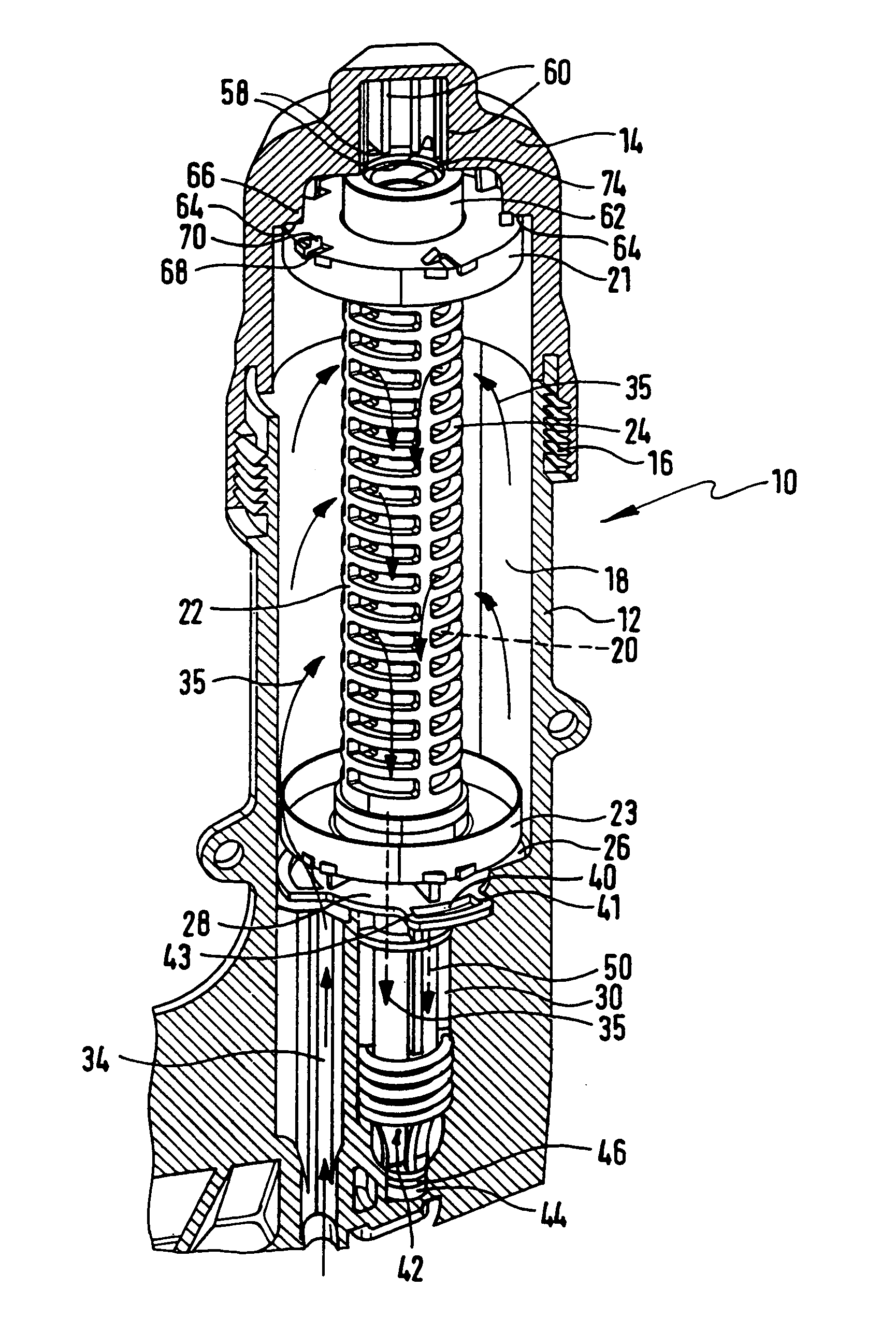
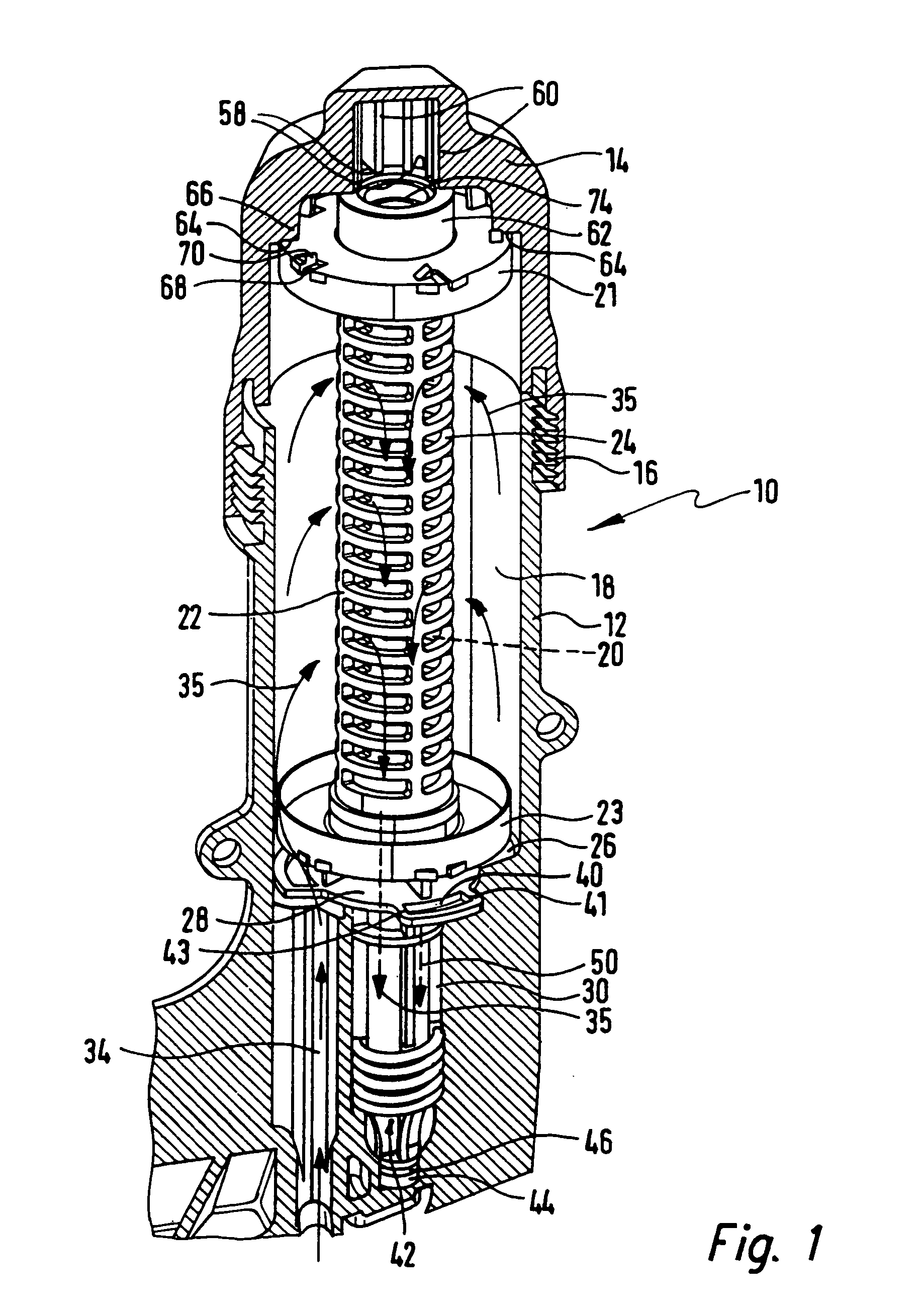
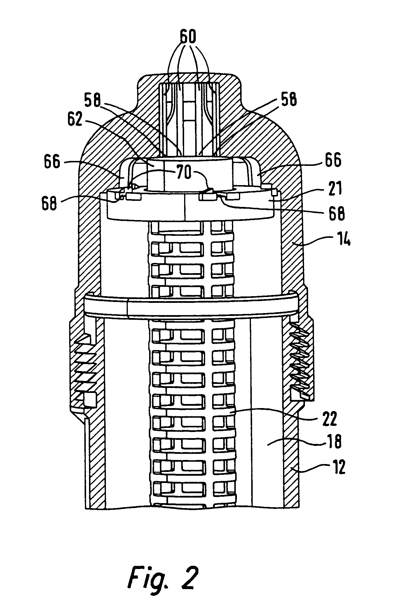
[0033]The oil filter assembly 10 shown in FIGS. 1 through 4 comprises a housing 12 that can be closed by a cover 14 via a thread 16. The housing 12 and the cover 14 form a receiving chamber 18 that houses a filter element 20 through which oil can flow in a radial direction. FIGS. 1 and 2 only show the two end caps 21, 23 of the filter element 20 for clear illustration of the function. The filter element 20 is supported by a supporting tube 22 which is can-shaped in the area where it is covered by the filter element 20. A plurality of openings 24 are provided on the supporting tube such that oil can flow through the supporting tube 22 in a radial direction. On its side facing a bottom 26 of the receiving chamber 18, the supporting tube comprises a circumferential annular collar 28 that is oriented in a radially outward direction. It is also possible to merely provide annular collar sections or feet instead of the annular collar 28.

[0034]A purified oil chamber 30 is provided downstrea...


PUM

PropertyMeasurementUnit
angle of rotationaaaaaaaaaa

Abstract

An oil filter assembly (10) has a receiving chamber (18) that can be closed by a cover element (14) and a spring-loaded supporting tube (22) that is fixed in the receiving chamber and is designed to receive a filter element (20) that can be radially traversed by oil. The supporting tube (22) is axially displaceable between an operating position and a drain position in such a way that, in the operating position when the receiving chamber is closed by the cover element (14), the tube closes a drain opening (42). When the receiving chamber is open in the drain position, the tube releases the drain opening. The supporting tube is mounted to rotate through a rotational angle that is limited by two rotational stops (41, 43) in the housing and the cover element has follower sections (66, 68, 70) that co-operate with the supporting tube and/or filter element to rotate the supporting tube through the rotational angle when the cover element is screwed on and/or unscrewed.

Description

[0001]This application is the national stage of PCT / EP2007 / 00476 filed on May 19, 2007 and claims Parts Convention Priority to DE10 2006 034 482.0 filed Jul. 21, 2006.BACKGROUND OF THE INVENTION[0002]The invention concerns an oil filter assembly comprising a receiving chamber that is disposed in a housing and can be closed by a cover element that can be screwed on, and a supporting tube that is fixed in the receiving chamber and is spring-loaded in the axial direction for receiving a filter element through which oil can flow in a radial direction, wherein the supporting tube is displaceably disposed in the axial direction between an operating position and a drain position such that, in the operating position, in which the cover element closes the receiving chamber, it closes a drain opening, and in the drain position, when the receiving chamber is opened, it opens a drain opening. In an oil filter assembly of this type, the supporting tube is fixed to the receiving chamber in such a...

Claims


Application Information

Patent Timeline
Patent Type & Authority Patents(United States)
IPC IPC(8): B01D35/16B01D27/08
CPCB01D29/21B01D35/153B01D29/96B01D35/16B01D2201/04
Inventor MAIER, JANPFITZER, FRIEDHELMMAUTE, ALEXANDERHEINZ, STEFANJUNGMANN, PETERKNOELL, MATTHIAS
Owner MANN HUMMEL GMBH
Why Eureka
Try Eureka