Air flow guidance element in the area between two interconnected railway vehicles

A technology for air guides and vehicles, which can be applied to vehicle parts, passages for connecting vehicles, railway car body parts, etc., and can solve problems such as unpleasant noise.

Inactive Publication Date: 2010-10-06
HUBNER GMBH
View PDF5 Cites 6 Cited by
  • Summary
  • Abstract
  • Description
  • Claims
  • Application Information

AI Technical Summary

Problems solved by technology

Associated with this, unpleasant noises are produced

Method used


Image

  • Air flow guidance element in the area between two interconnected railway vehicles
  • Air flow guidance element in the area between two interconnected railway vehicles
  • Air flow guidance element in the area between two interconnected railway vehicles

Examples


Embodiment Construction

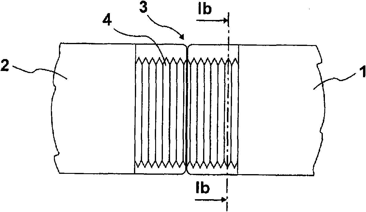
[0018] according to Figure 1a , the two schematically shown vehicles 1 and 2 are connected via a transition 3 with a tunnel-shaped bellows 4 . For greater clarity, the transition plate, which is part of the transition, has been omitted from the figure, as has the coupling of the two vehicles.

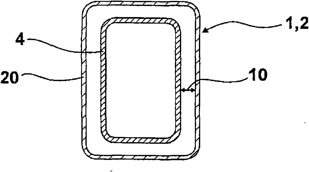
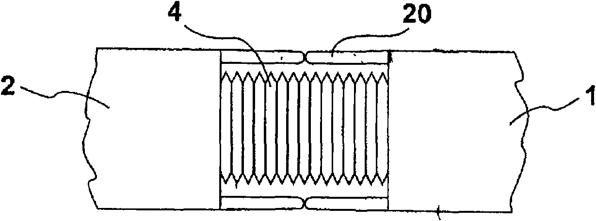
[0019] as in Figure 1b and figure 2 As can be seen in , the diameters of compartments 1 and 2 are greater than the bellows marked with 4. The distance between the outer wall of the car body 1 and the bellows 4 is referred to as the gap 10 . The gap 10 is covered by a pair of air guides comprising two air guides 20 which are circumferential, U-shaped or only laterally—on both sides of the vehicle (right and left) - Mounted in an extended manner on the end side of each body of the vehicle 1 , 2 .

[0020] exist Figure 3a , 3b The design scheme of the air guide 20 is given in . A support body 21 is provided here, which is arranged in a recess 22 of the receiving rail 30 . The r...


PUM


Abstract

The invention relates to an air guidance element which is mounted in a transition portion area between two interconnected railway vehicles in a way substantially aligned with a housing. A cross section of the air guidance element (20) is designed to be a cone or an arc and the air guidance element has at least an elastically deformed supporter (21).

Description

technical field [0001] The invention relates to a wind deflector for installation substantially flush with a housing in the region of a transition between two mutually articulated vehicles. Background technique [0002] The mutually articulated vehicles are connected to each other by so-called transitions. Such a transition comprises, in addition to the transition plate, a bellows which at least surround the transition plate in a tunnel-like manner. In this case, the radial extent of the tunnel bellows, especially in the region of the side walls, is smaller than the radial extent of the carriage body. This means that there is a distance between the outer vehicle wall and the bellows. The distances are present at least in the region of the side walls but also in the region of the top. [0003] Particularly at higher speeds, considerable eddies are formed in the region of the transition, which lead to flow losses, which in turn lead to an increased drive power. This is esp...

Claims


Application Information

Patent Timeline
Patent Type & Authority Applications(China)
IPC IPC(8): B61D17/22
CPCB60D5/003B61D17/02B61D17/20Y02T30/32Y02T30/00
Inventor W·波格利洛L·克吕格尔
Owner HUBNER GMBH
Why Eureka
Try Eureka