Exhaust gas system for exhaust gas after-treatment

An exhaust system and exhaust gas technology, applied in exhaust treatment, exhaust equipment, air quality improvement, etc., can solve the problems of increasing fuel consumption, exhaust system blockage, increasing harmful substance emissions, etc., and achieve the effect of avoiding deposition

Pending Publication Date: 2020-12-18
ROBERT BOSCH GMBH
View PDF0 Cites 0 Cited by
  • Summary
  • Abstract
  • Description
  • Claims
  • Application Information

AI Technical Summary

Problems solved by technology

[0004] However, it has been shown that there is a risk that a part of the reducing agent injected or fed into the exhaust system does not evaporate completely and, for example, sticks to the mixing elements and / or the boundaries of the exhaust system and forms deposits which can negatively influence the reduction of harmful substances , so that this deposit e.g. increases fuel consumption and / or increases emissions of harmful substances and even leads to clogging of the exhaust system

Method used


Image

  • Exhaust gas system for exhaust gas after-treatment
  • Exhaust gas system for exhaust gas after-treatment

Examples


Embodiment Construction

[0022] Hereinafter, embodiments of the present invention will be described with reference to the drawings. The same reference numerals designate the same or corresponding elements.

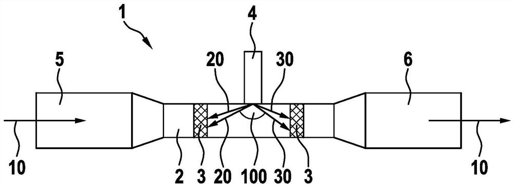
[0023] figure 1 A first exemplary embodiment of an exhaust gas system 1 is shown, which has a straight section 2 through which the exhaust gas flows in the gas flow direction indicated by the arrow 10 . The two mixing elements 3 are arranged at a distance relative to each other in the straight section 2 of the exhaust gas system 1 .

[0024] A metering module 4 is arranged between the two mixing elements 3 , which is provided for injecting or feeding in a fluid. The fluid may be a fluid reducing agent, especially a urea solution, which should be mixed with the exhaust gas. For this purpose, the metering module 4 injects the fluid into the exhaust gas in the form of fine droplets in the direction of the mixing element 3 . The metering module 4 is arranged such that a mixing element 3 is arrange...


PUM


Abstract

The invention relates to an exhaust gas system (1) in a motor vehicle, comprising: a dosing module (4) for feeding a fluid, in particular a fluid reducing agent, into the exhaust gas system (1); and at least two mixing elements (3), which are designed to mix the exhaust gas flowing through the exhaust gas system (1) with the fed fluid, wherein the dosing module (4) is designed to feed a part of the fluid into the exhaust gas system (1) substantially opposite the gas flow direction (10) and to feed another part of the fluid into the exhaust gas system (1) substantially in the gas flow direction(10), at least one mixing element (3) is arranged upstream of the dosing module (4) in the exhaust gas system (1) and at least one mixing element (3) is arranged downstream of the dosing module (4) in the exhaust gas system (1).

Description

technical field [0001] The invention relates to an exhaust gas system in a motor vehicle having at least one metering module for feeding or injecting a fluid, in particular a fluid reducing agent, into the exhaust system; and having at least two mixing elements , the mixing element is designed to mix at least one gas flowing through the exhaust gas system, in particular exhaust gas, with the fed-in fluid. The fluid is, for example, a fluid reducing agent, especially a urea solution. Background technique [0002] In order to keep the air pollution caused by the emitted exhaust gases as low as possible, aftertreatment of the exhaust gases is necessary. For such exhaust gas aftertreatment of internal combustion engines, especially diesel engines, in particular so-called SCR systems (SCR = "Selective Catalytic Reduction"), with which the nitrogen oxides contained in the exhaust gas are reduced ( NOx). [0003] In order to reduce nitrogen oxides in the exhaust gas, a reducing ...

Claims


Application Information

Patent Timeline
Patent Type & Authority Applications(China)
IPC IPC(8): F01N3/10F01N3/20
CPCF01N3/10F01N3/2066F01N2570/10F01N2570/12F01N2570/14F01N3/206F01N3/2892F01N2240/20F01N2610/01F01N2610/02F01N2610/1453Y02T10/12Y02A50/20
Inventor B·达姆森
Owner ROBERT BOSCH GMBH
Why Eureka
Try Eureka