Injection chamber for a metal injection machine

a metal injection machine and injection chamber technology, applied in the field of injection chambers, can solve the problems of affecting the quality of liquid metal injection, affecting the operation of the injection chamber, and destroying the piston chamber assembly

Inactive Publication Date: 2011-01-20
W FISCHER TECNICA
View PDF1 Cites 17 Cited by
  • Summary
  • Abstract
  • Description
  • Claims
  • Application Information

AI Technical Summary

Benefits of technology

[0015]The construction proposed by the invention permits the inner region of the supply portion, which is submitted to the impact of the charge of molten metal poured in the injection chamber, to be protected by the insert formed in a metallic alloy or any other high temperature-resistant material, preventing early erosion of this region and the consequent inconveniences of said erosion.
[0016]Besides the provision o

Problems solved by technology

As is known by those skilled in the art, the erosion of the inner region of the injection chamber CI allows the molten metal to be housed in this eroded region, impairing the liquid metal injection process, as well as damaging the chamber and the piston in a degree capable of causing the binding of the piston and the consequent destruction of the piston-chamber assembly.
The inconvenience related to the early erosion mentioned above is even more harmful to the machine and to the efficiency of its operation, when the temperature control system of the tubular body is designed only for cooling the region subjected to the heating provoked by the pouring of the molten metal MF.
The limitations regarding the wall thickness of the tubular body 10 impair the provision of linings and also the adequate dimensioning of the temperature control system, making

Method used


Image

  • Injection chamber for a metal injection machine
  • Injection chamber for a metal injection machine
  • Injection chamber for a metal injection machine

Examples


Embodiment Construction

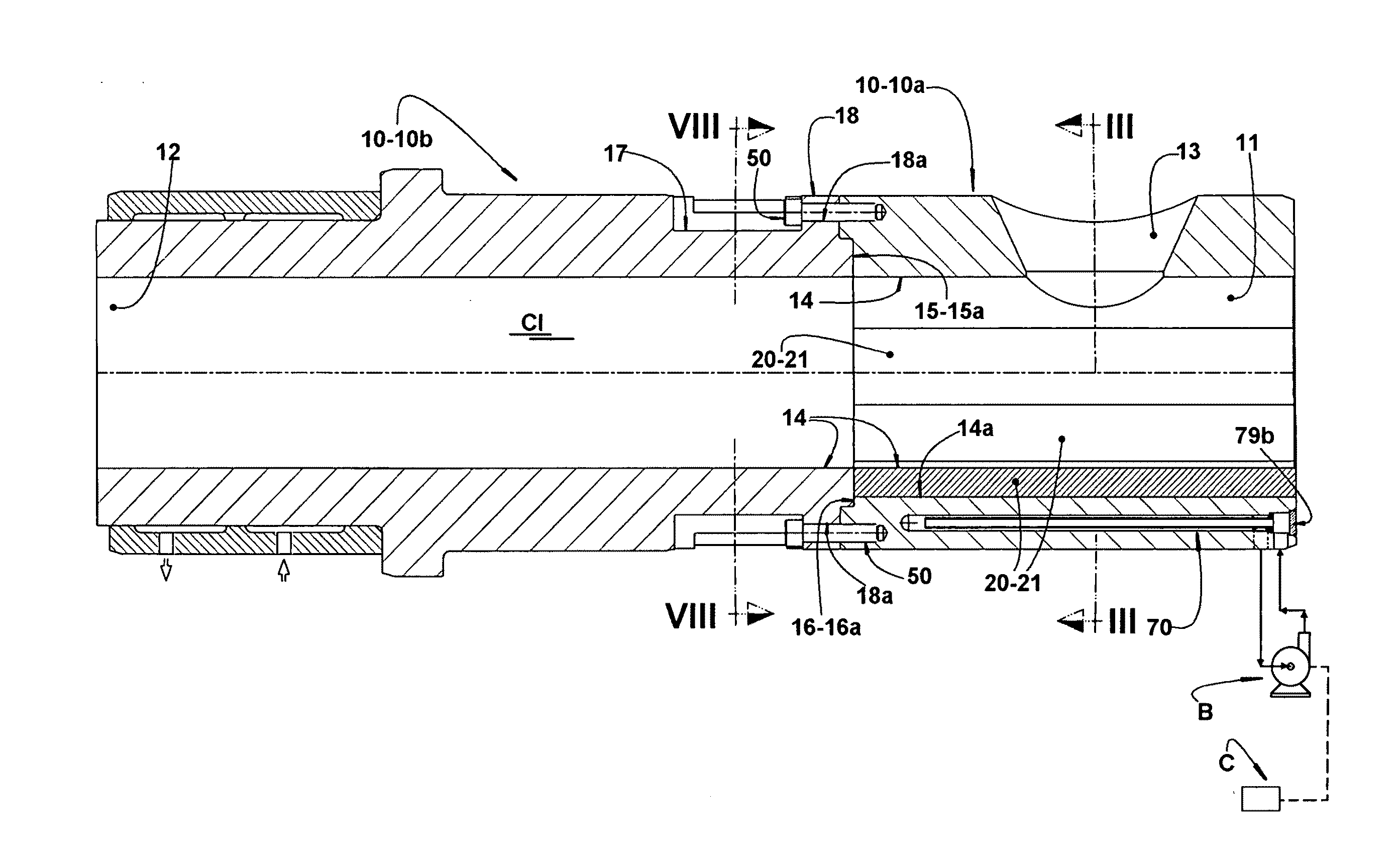
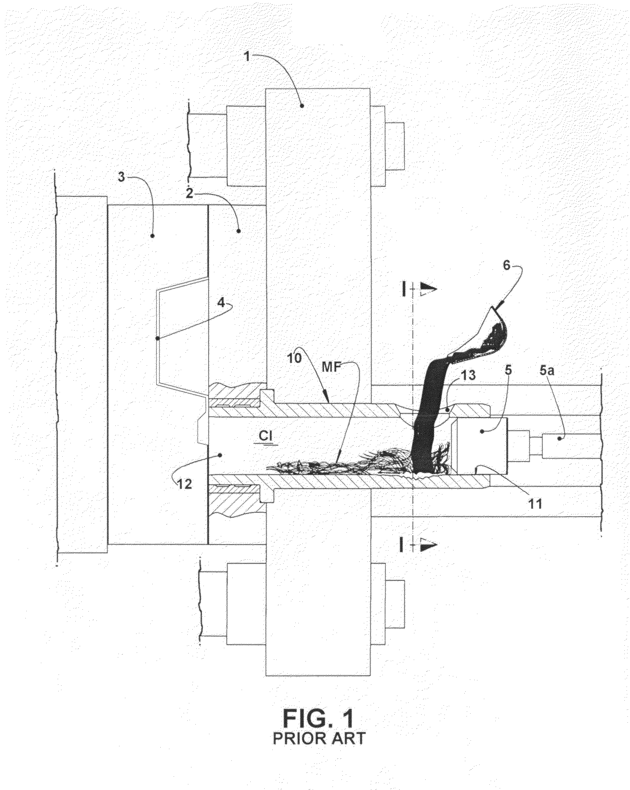
[0031]As illustrated and already mentioned, the invention refers to an injection chamber to be applied to an injection machine used in the injection molding, by pressure, of pieces formed in metallic alloys of aluminum and other light metals, said injection machine being of the type described in the introduction of the present specification and illustrated in FIG. 1 of the enclosed drawings.

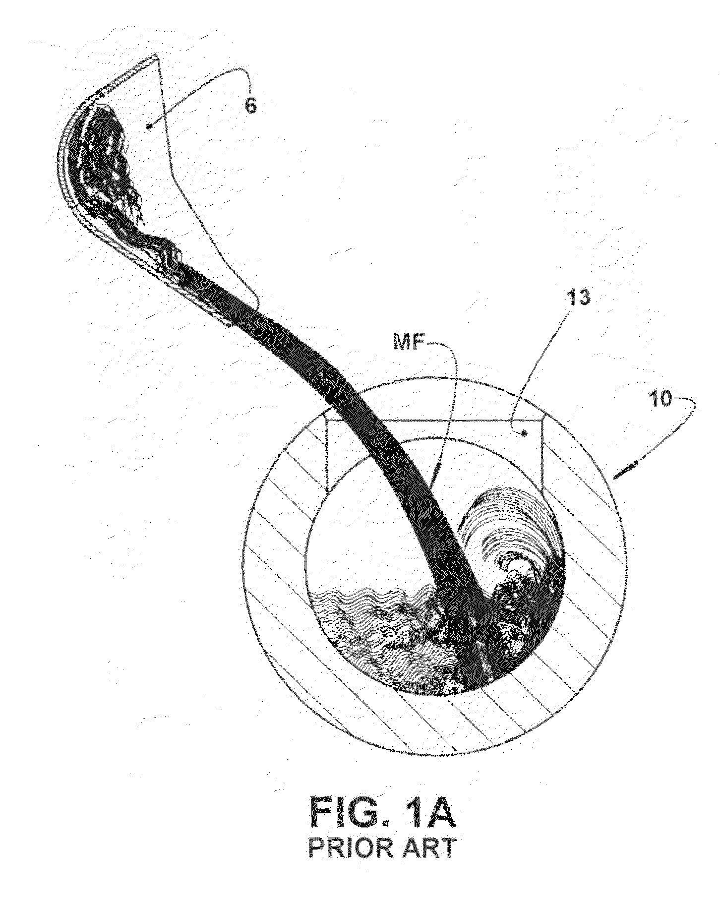
[0032]The injection chamber CI comprises a tubular body 10, having a cylindrical inner surface 14 and being formed by a supply portion 10a provided with a closed mounting end 11, which is trespassed by the rod 5a of the piston 5 and provided with a radial supply window 13, through which a charge of molten metal MF is poured in the interior of the injection chamber CI. The tubular body 10 has also an injection portion 10b, coaxially incorporated to the supply portion 10a and provided with an outlet end 12 opened to the interior of the molding cavity 4.

[0033]The piston 5 is axially displaced in the...


PUM

PropertyMeasurementUnit
Displacementaaaaaaaaaa

Abstract

The injection chamber (CI) includes a tubular body formed by a supply portion, having a radial supply window to receive a charge of molten metal (MF) and in which is incorporated an injection portion provided with an outlet end opened to the interior of a molding cavity. A piston is provided to be displaced in the interior of the tubular body to inject the molten metal (MF) in the molding cavity. The supply portion has its inner region, which receives the pouring impact of the charge of molten metal (MF), lined by an insert formed in a high melting point material and presenting an inner contour in the form of a circle arc coinciding with that of the supply and injection portions.

Description

FIELD OF THE INVENTION[0001]The present invention refers to an injection chamber to be operatively coupled to a molten metal injection machine, used in the injection molding, by pressure, of pieces formed in metallic alloys of aluminum or other light metals, said injection chamber being constructed to better resist early erosion in its inner region, in which the hot molten metal is poured, and also to minimize its temperature variations upon operation, avoiding the damaging effects of the thermal expansion in the operation of the injection piston, as well as of an untimely and excessive cooling of the molten metal being processed.BACKGROUND OF THE INVENTION[0002]As illustrated in FIG. 1 of the enclosed drawings, the known injection machines of liquid metal, generally aluminum, are provided with a base portion 1, in which a fixed mold portion 2 is affixed, configured to cooperate with a movable mold portion 3, which is displaced between an open position (not illustrated) and a closed...

Claims


Application Information

Patent Timeline
IPC IPC(8): B22D35/04B22D17/00
CPCB22D17/2023
Inventor FISCHER, WILMAR
Owner W FISCHER TECNICA
Why Eureka
Try Eureka