
Beverage bottling plant for filling containers, such as bottles and cans, with a liquid beverage, a filling machine for filling containers with a liquid, and a method for filling containers with the filling machine

a beverage bottling plant and container technology, which is applied in the field of beverage bottling plant for filling containers, can solve the problems of inability to prevent interruptions in the filling process, inability to reliably kill germs in the liquid and in the filling elements that can contaminate the liquid being bottled, and inability to prevent interruptions. the effect of cooling the filling elements

Inactive Publication Date: 2007-07-17
KHS GMBH
View PDF21 Cites 20 Cited by
  • Summary
  • Abstract
  • Description
  • Claims
  • Application Information

AI Technical Summary

Benefits of technology

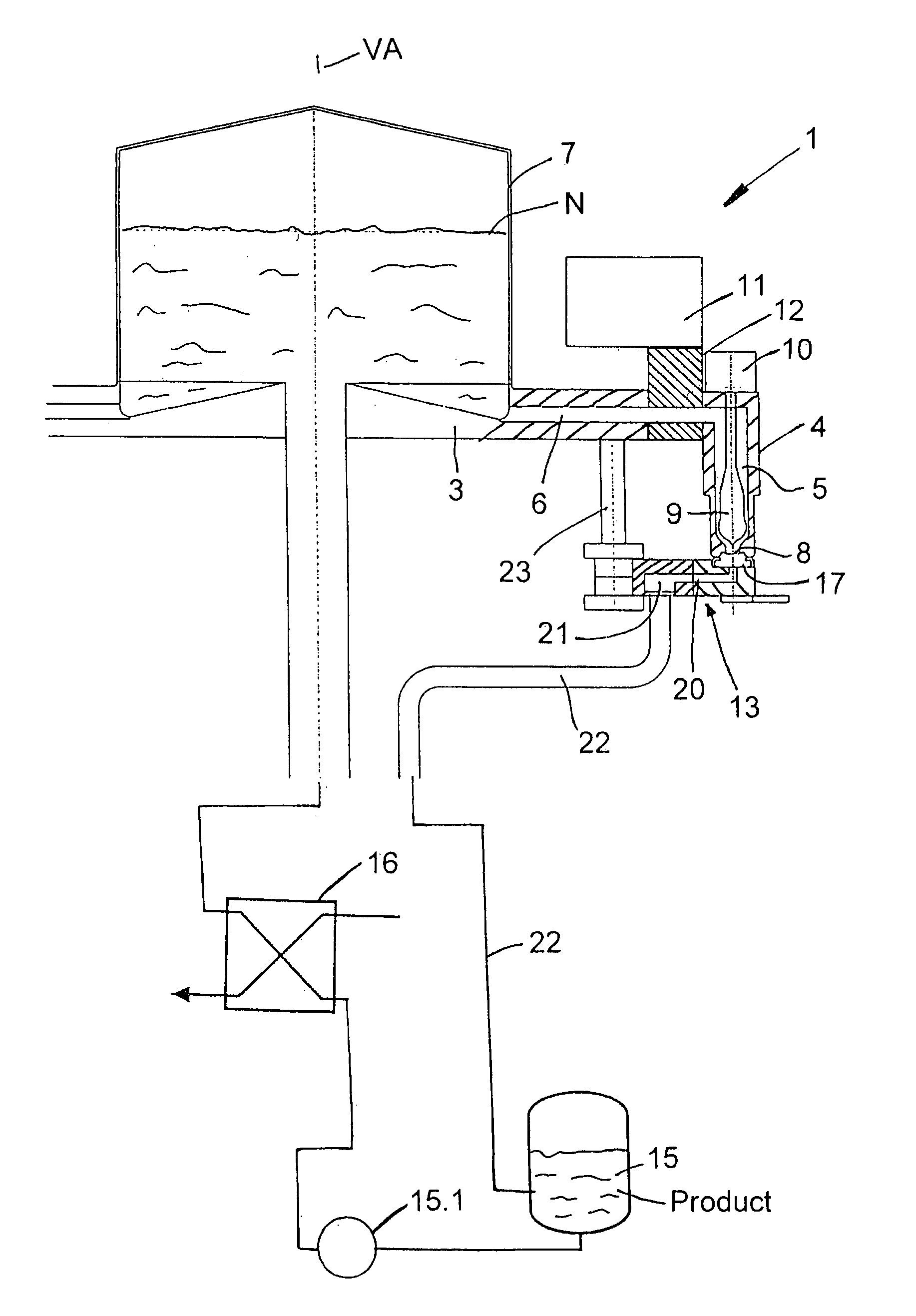
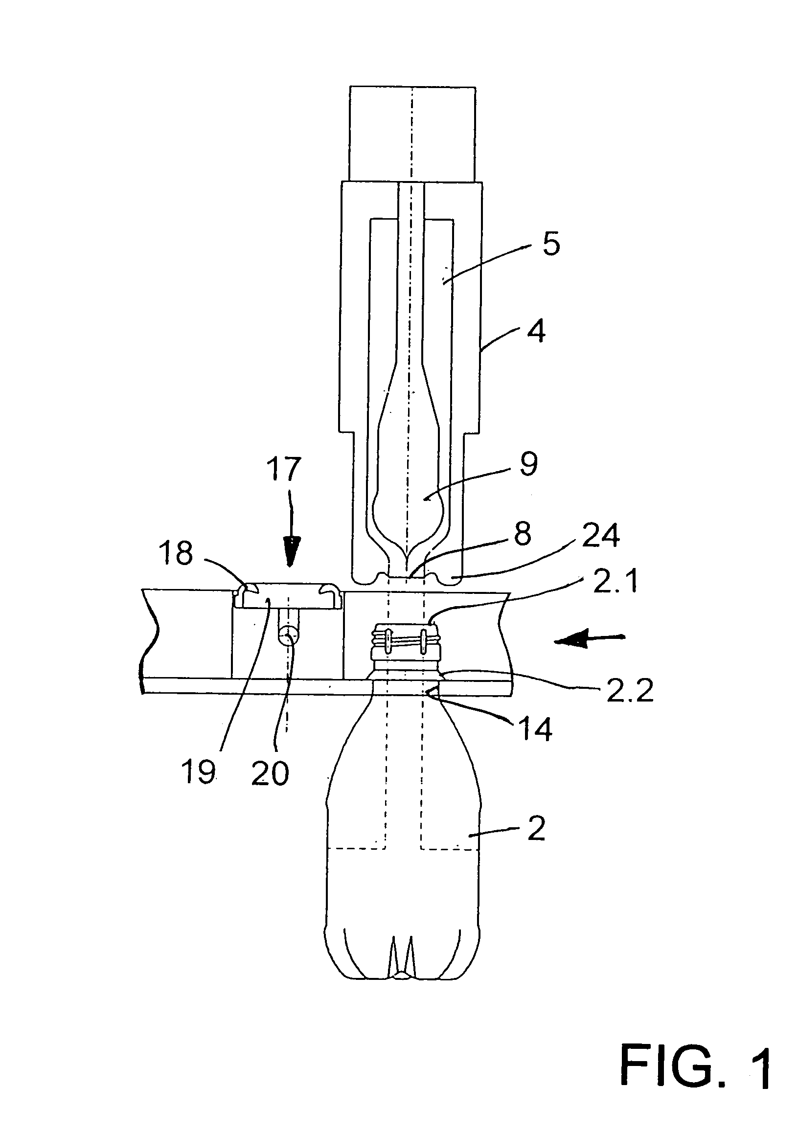
The present invention relates to a filling machine for bottling hot liquid. The invention provides a solution to prevent the cooling of the filling elements and the growth of germs during an interruption of the hot bottling process. The invention involves closing and connecting the filling elements and their liquid ducts to create a well inside the machine's liquid path, which ensures that the hot liquid continues to flow through the filling elements as the machine rotates. This prevents the filling elements from cooling down and retains the hot liquid in them, which can be a potential health hazard.

Problems solved by technology

During hot bottling, however, it is impossible to prevent interruptions of the filling process, for example as a result of disruptions in the feed of the empty containers and / or during the removal of the filled containers.
During such interruptions, there is a risk of cooling of the liquid that is then held back in the closed filling elements or is just approaching the closed filling elements, as well as a cooling of the filling elements themselves, so that the germs in the liquid and in the filling elements that can contaminate the liquid being bottled can no longer be reliably killed and / or prevented.

Method used


Image

  • Beverage bottling plant for filling containers, such as bottles and cans, with a liquid beverage, a filling machine for filling containers with a liquid, and a method for filling containers with the filling machine
  • Beverage bottling plant for filling containers, such as bottles and cans, with a liquid beverage, a filling machine for filling containers with a liquid, and a method for filling containers with the filling machine
  • Beverage bottling plant for filling containers, such as bottles and cans, with a liquid beverage, a filling machine for filling containers with a liquid, and a method for filling containers with the filling machine

Examples


Embodiment Construction

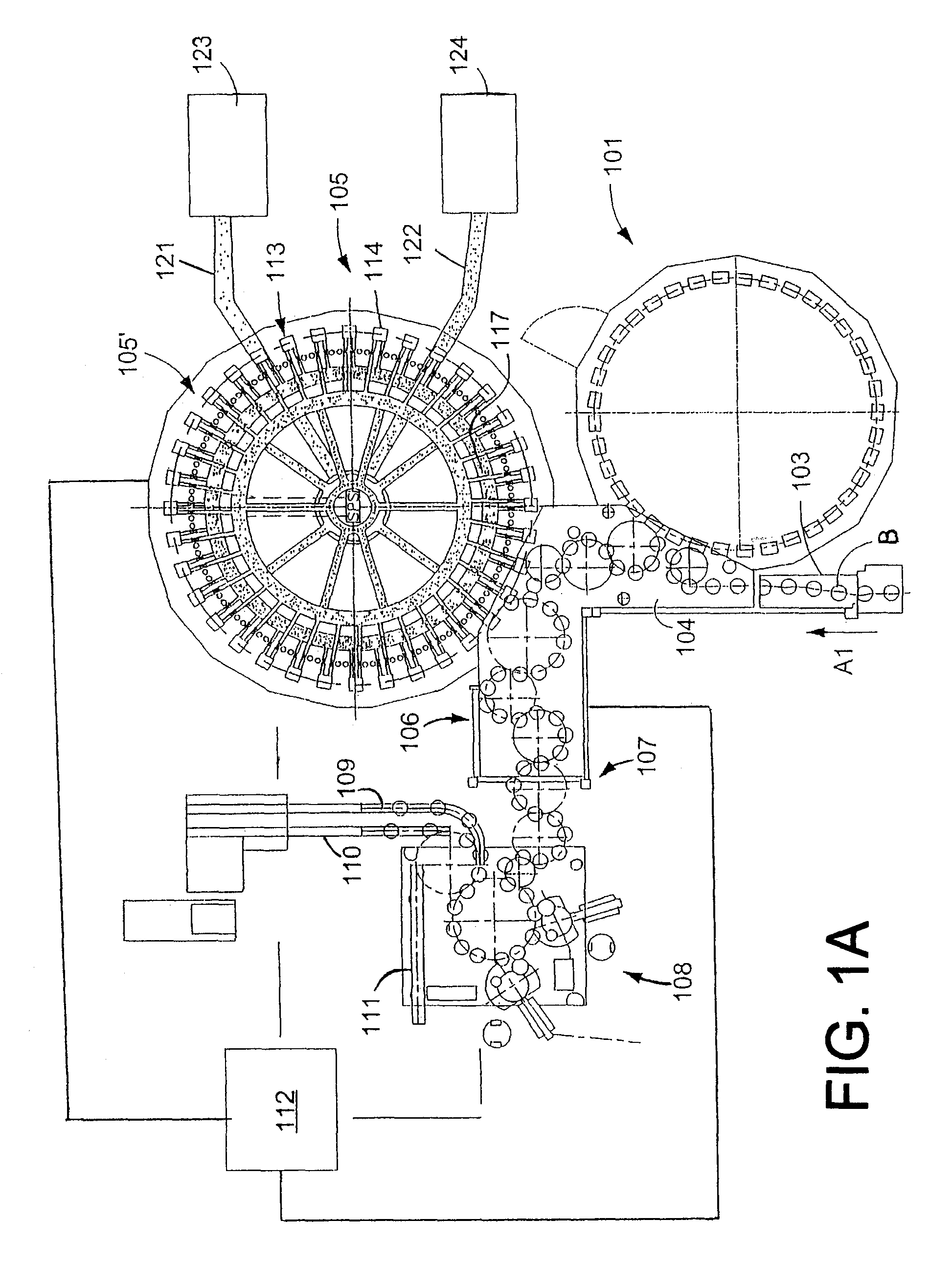
[0022]FIG. 1A shows schematically the main components of one possible embodiment example of a system for filling containers, specifically, a beverage bottling plant for filling bottles B with at least one liquid beverage, in accordance with at least one possible embodiment, in which system or plant could possibly be utilized at least one aspect, or several aspects, of the embodiments disclosed herein.

[0023]FIG. 1A shows a rinsing arrangement or rinsing station 101, to which the containers, namely bottles B, are fed in the direction of travel as indicated by the arrow A1, by a first conveyer arrangement 103, which can be a linear conveyor or a combination of a linear conveyor and a starwheel. Downstream of the rinsing arrangement or rinsing station 101, in the direction of travel as indicated by the arrow A1, the rinsed bottles B are transported to a beverage filling machine 105 by a second conveyer arrangement 104 that is formed, for example, by one or more starwheels that introduce...


PUM

PropertyMeasurementUnit
temperaturesaaaaaaaaaa
liquidaaaaaaaaaa

Abstract

A method for hot bottling of a liquid in bottles, kegs or similar containers using a filling machine that has a plurality of filling elements, each filling element has a liquid duct disposed at a dispensing opening and a valve for dispensing the hot liquid to the container, the liquid being bottled in the filling elements is substantially continuously conveyed in the hot condition in a circuit comprising a flow path that includes the filling elements and the liquid ducts from a source for the hot liquid being bottled to a reservoir during an interruption of the filling process in order to reduce the cooling of the liquid being bottled in the filling elements and / or to prevent the cooling of the filling elements.

Description

BACKGROUND[0001]1. Technical Field[0002]The present application relates to a beverage bottling plant for filling containers, such as bottles and cans, with a liquid beverage, a filling machine for filling containers with a liquid, and a method for filling containers with the filling machine.[0003]2. Background Information[0004]A beverage bottling plant for filling bottles with a liquid beverage filling material can possibly comprise a beverage filling machine with a plurality of beverage filling positions, each beverage filling position having a beverage filling device for filling bottles with liquid beverage filling material. The filling devices may have an apparatus being configured to introduce a predetermined volume of liquid beverage filling material into the interior of bottles to a substantially predetermined level of liquid beverage filling material, and the apparatus configured to introduce a predetermined flow of liquid beverage filling material comprising apparatus being ...

Claims


Application Information

Patent Timeline
Patent Type & Authority Patents(United States)
IPC IPC(8): B65B3/04B67C3/28B67C3/14
CPCB67C3/045B67C3/281
Inventor CLUSSERATH, LUDWIGTILL, VOLKERKRULITSCH, DIETER-RUDOLF
Owner KHS GMBH
Learn More