Arrangement for recirculation of exhaust gases in a supercharged combustion engine

a combustion engine and exhaust gas technology, applied in the direction of machines/engines, mechanical equipment, non-fuel substance addition to fuel, etc., can solve the problem that the control process may still be significantly more complex

Active Publication Date: 2009-12-31
SCANIA CV AB
View PDF6 Cites 21 Cited by
  • Summary
  • Abstract
  • Description
  • Claims
  • Application Information

AI Technical Summary

Benefits of technology

[0010]According to an embodiment of the present invention, the arrangement comprises a manually settable control device by which it is possible to place the valve means in said first position or said second position. Such a control device enables a driver to take a decision and determine in which position the valve means should be placed and when it should be changed. The driver can make such a decision on the basis, for example, of knowing the temperature of the surrounding air and the prevailing weather conditions. With advantage, however, the arrangement comprises a control unit adapted to receiving information concerning at least one parameter for deciding whether there is risk of ice formation in the EGR cooler and to placing the valve means in the second position when it decides there is such a risk. Thus the control unit can automatically place the valve means in an appropriate position during operation of the combustion engine. The control unit may be a computer unit provided with software adapted to deciding in which position to place the valve means on the basis of information about one or more guiding parameters. Preferably, the arrangement comprises a temperature sensor adapted to detecting the temperature of the surrounding air and the control unit is adapted to using information from said temperature sensor to decide whether there is risk of ice formation in the EGR cooler. By a simple control process, the control unit will place the valve means in the first position when the temperature sensor indicates a temperature above 0° C. and in the second position when the temperature sensor indicates a temperature below 0° C. The control process may nevertheless be significantly more complex. With a more complex control process, it is possible to detect situations where it is appropriate to use the air-cooled EGR cooler even if the surrounding air is at a temperature below 0° C.
[0011]According to a preferred embodiment of the invention, the control unit may be adapted to using knowledge of a parameter which is related to the exhaust flow through the return line to decide whether there is risk of ice formation in the EGR cooler. When a larger exhaust flow is led through the EGR cooler, the exhaust gases cannot be cooled to as low a temperature as when a smaller exhaust flow is led through the it. In situations where an ambient temperature somewhat below 0° C. prevails, the control unit can therefore place the valve means in the first position when large amounts of exhaust gases are returned via the return line and place the valve means in the second position when smaller amounts of exhaust gases are returned via the return line. The control unit may also be adapted to using knowledge of a parameter which is related to the flow velocity of the surrounding air through the EGR cooler to decide whether there is risk of ice formation in the EGR cooler. The flow velocity of the surrounding air is a parameter which determines how effectively the recirculating exhaust gases are cooled in the EGR cooler. If the cooling air flows at a high velocity through the EGR cooler, the result is more effective cooling of the recirculating exhaust gases than when the air is at a lower velocity.
[0012]According to a preferred embodiment of the invention, the arrangement comprises a coolant-cooled EGR cooler adapted to cooling the recirculating exhaust gases in a first stage before they are cooled in the air-cooled EGR cooler in a second stage. Assurance is thus afforded that the exhaust gases will undergo acceptable cooling in all circumstances. With advantage, the coolant of the cooling system for the combustion engine is used for cooling the recirculating exhaust gases in the first stage. The recirculating exhaust gases can thus be provided with effective cooling in the first stage. The EGR cooler may comprise a first tank for receiving recirculating exhaust gases, a cooling portion through which the recirculating exhaust gases flow during cooling by surrounding air, and a second tank for receiving the recirculating exhaust gases after they have been cooled in the cooling portion. Such an EGR cooler may with advantage be fitted at a front portion of a vehicle where it has air at the temperature of the surroundings flowing through it. The valve means may be arranged in the first tank and said bypass line may extend between the first tank and the second tank, making it possible for the bypass to constitute an integral part of the EGR cooler and be fitted together with it as a composite unit.

Problems solved by technology

By a simple control process, the control unit will place the valve means in the first position when the temperature sensor indicates a temperature above 0° C. and in the second position when the temperature sensor indicates a temperature below 0° C. The control process may nevertheless be significantly more complex.

Method used


Image

  • Arrangement for recirculation of exhaust gases in a supercharged combustion engine
  • Arrangement for recirculation of exhaust gases in a supercharged combustion engine
  • Arrangement for recirculation of exhaust gases in a supercharged combustion engine

Examples


Embodiment Construction

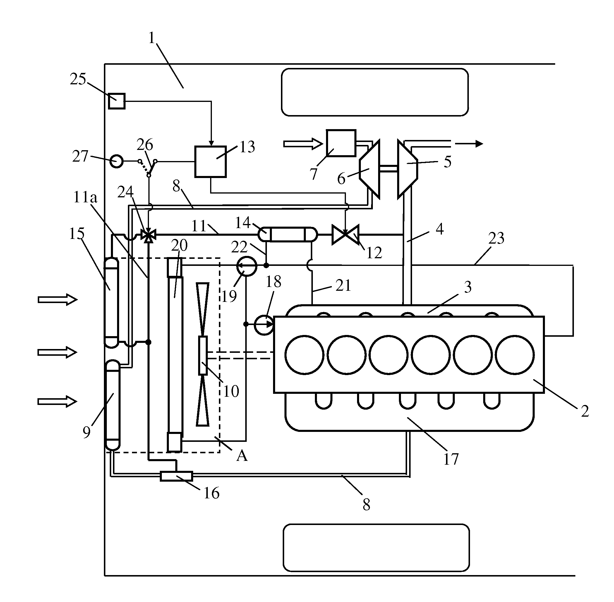
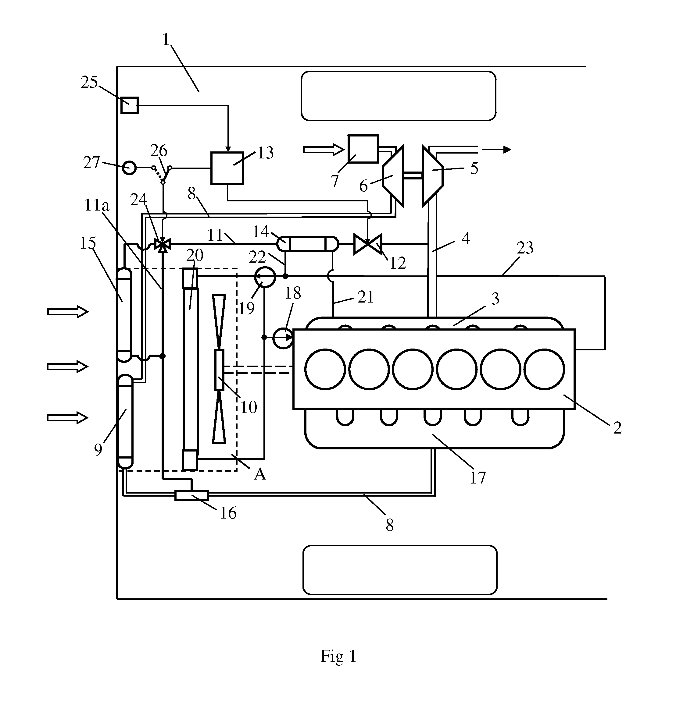
[0016]FIG. 1 depicts a vehicle 1 powered by a supercharged combustion engine 2. The vehicle 1 may be a heavy vehicle powered by a supercharged diesel engine. The exhaust gases from the cylinders of the combustion engine 2 are led via an exhaust manifold 3 to an exhaust line 4. The exhaust gases in the exhaust line 4, which are at above atmospheric pressure, are led to a turbine 5 of a turbo unit. The turbine 5 is thus provided with driving power which is transferred, via a connection, to a compressor 6. The compressor 6 compresses air which is led into an inlet line 8 via an air filter 7. A charge air cooler 9 is arranged in the inlet line 8. The charge air cooler 9 is arranged in a region A at a front portion of the vehicle 1. The function of the charge air cooler 9 is to cool the compressed air before it is led to the combustion engine 2. The compressed air is cooled in the charge air cooler 9 by surrounding air which is caused to flow through the charge air cooler 9 by a radiator...


PUM


Abstract

An arrangement for recirculation of exhaust gases of a supercharged combustion engine includes a return line for recirculating exhaust gases, an air-cooled EGR cooler and a bypass line having an extent such that it can lead recirculating exhaust gases past the EGR cooler. A valve is operable to be placed in a first position to lead the whole flow of recirculating exhaust gases through the EGR cooler during situations where there is no risk of ice formation in the EGR cooler, and in a second position to lead the whole flow of recirculating exhaust gases through the bypass line during situations where there is risk of ice formation in the EGR cooler.

Description

CROSS REFERENCE TO RELATED APPLICATION[0001]The present application is a 35 U.S.C. §§ 371 national phase conversion of PCT / SE2007 / 050836, filed Nov. 12, 2007, which claims priority of Swedish Application No. 0602517-5, filed Nov. 27, 2006, the disclosure of which is incorporated by reference herein. The PCT International Application was published in the English language.BACKGROUND TO THE INVENTION, AND STATE OF THE ART[0002]The present invention relates to an arrangement for recirculation of exhaust gases of a supercharged combustion engine and to controlled cooling of the recirculating exhaust gases.[0003]The amount of air which can be supplied to a supercharged combustion engine depends on the pressure of the air but also on the temperature of the air. Supplying a largest possible amount of air to the combustion engine entails cooling the compressed air in a charge air cooler before it is led to the combustion engine. The compressed air is cooled, usually in a charge air cooler si...

Claims


Application Information

Patent Timeline
Patent Type & Authority Applications(United States)
IPC IPC(8): F02B33/44F02M25/07
CPCF02B29/0431F02M25/0707F02M25/0728F02M25/073Y02T10/121F02M25/0732F02M25/0736F02M25/0738F02M25/0731F02M26/31F02M26/05F02M26/25F02M26/27F02M26/28F02M26/24F02M26/33
Inventor KARDOS, ZOLTANPETTERSSON, RICKARDALSTERDAL, TOMASNYREN, HENRIK
Owner SCANIA CV AB
Why Eureka
Try Eureka