
Apparatus and method for improved transient response in an electromagnetically controlled x-ray tube

a technology of electromagnetic control and x-ray tube, which is applied in the field of diagnostic imaging, can solve the problems of limiting the design options for forming electron beams from emitters, affecting the design of x-ray tube throats, and not being typically optimized for image quality or thermal focal spot loading

Active Publication Date: 2012-10-09
GENERAL ELECTRIC CO
View PDF5 Cites 1 Cited by
  • Summary
  • Abstract
  • Description
  • Claims
  • Application Information

AI Technical Summary

Benefits of technology

"The invention relates to an x-ray tube assembly and an imaging system. The x-ray tube assembly includes a vacuum enclosure with a throat portion having recesses to break up eddy currents generated therein. The assembly also includes a target positioned within the target portion of the vacuum enclosure and a cathode positioned within the cathode portion of the vacuum enclosure. The cathode is configured to emit a stream of electrons through the throat portion towards the target. The imaging system includes a rotatable gantry with an opening for receiving an object to be scanned, a table positioned within the opening, and an x-ray tube coupled to the rotatable gantry. The x-ray tube includes a vacuum chamber with a target portion housing a target, a cathode portion housing a cathode, and a throat portion comprising a first magnetic field section susceptible to eddy current generation. The first electron manipulation coil is mounted on the x-ray tube and aligned with the first magnetic field section of the throat portion such that the first plurality of recesses break up eddy currents generated by the first magnetic field. The technical effects of the invention include improved image quality and reduced noise in the obtained images."

Problems solved by technology

However, the shape of the filament is not typically optimized for image quality or for thermal focal spot loading.
Therefore, the range of design options for forming the electron beam from the emitter may be limited by the filament shape, when considering electrically resistive materials as the emitter source.
However, when current in the electromagnets is rapidly changed to generate the changing magnetic field, eddy currents are generated in the vacuum vessel wall that opposes the magnetic field penetration inside the x-ray tube.
The configuration of the x-ray tube throat is subject to a number of design constraints.

Method used


Image

  • Apparatus and method for improved transient response in an electromagnetically controlled x-ray tube
  • Apparatus and method for improved transient response in an electromagnetically controlled x-ray tube
  • Apparatus and method for improved transient response in an electromagnetically controlled x-ray tube

Examples


Embodiment Construction

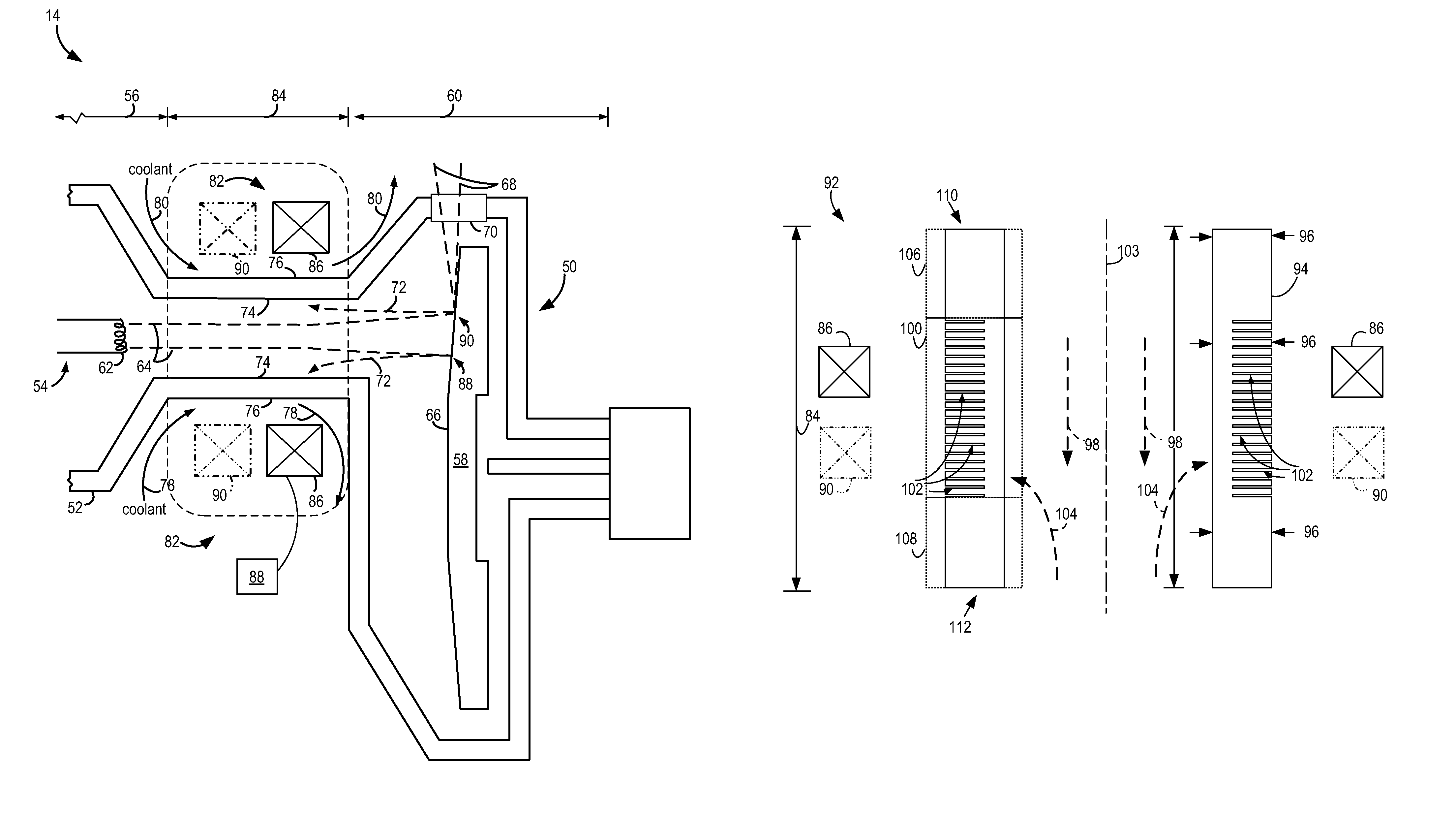
[0024]The operating environment of embodiments of the invention is described with respect to a computed tomography (CT) system. It will be appreciated by those skilled in the art that embodiments of the invention are equally applicable for use with any multi-slice configuration. Moreover, embodiments of the invention will be described with respect to the detection and conversion of x-rays. However, one skilled in the art will further appreciate that embodiments of the invention are equally applicable for the detection and conversion of other high frequency electromagnetic energy. Embodiments of the invention will be described with respect to a “third generation” CT scanner, but is equally applicable with other CT systems, surgical C-arm systems, and other x-ray tomography systems as well as numerous other medical imaging systems implementing an x-ray tube, such as x-ray or mammography systems.

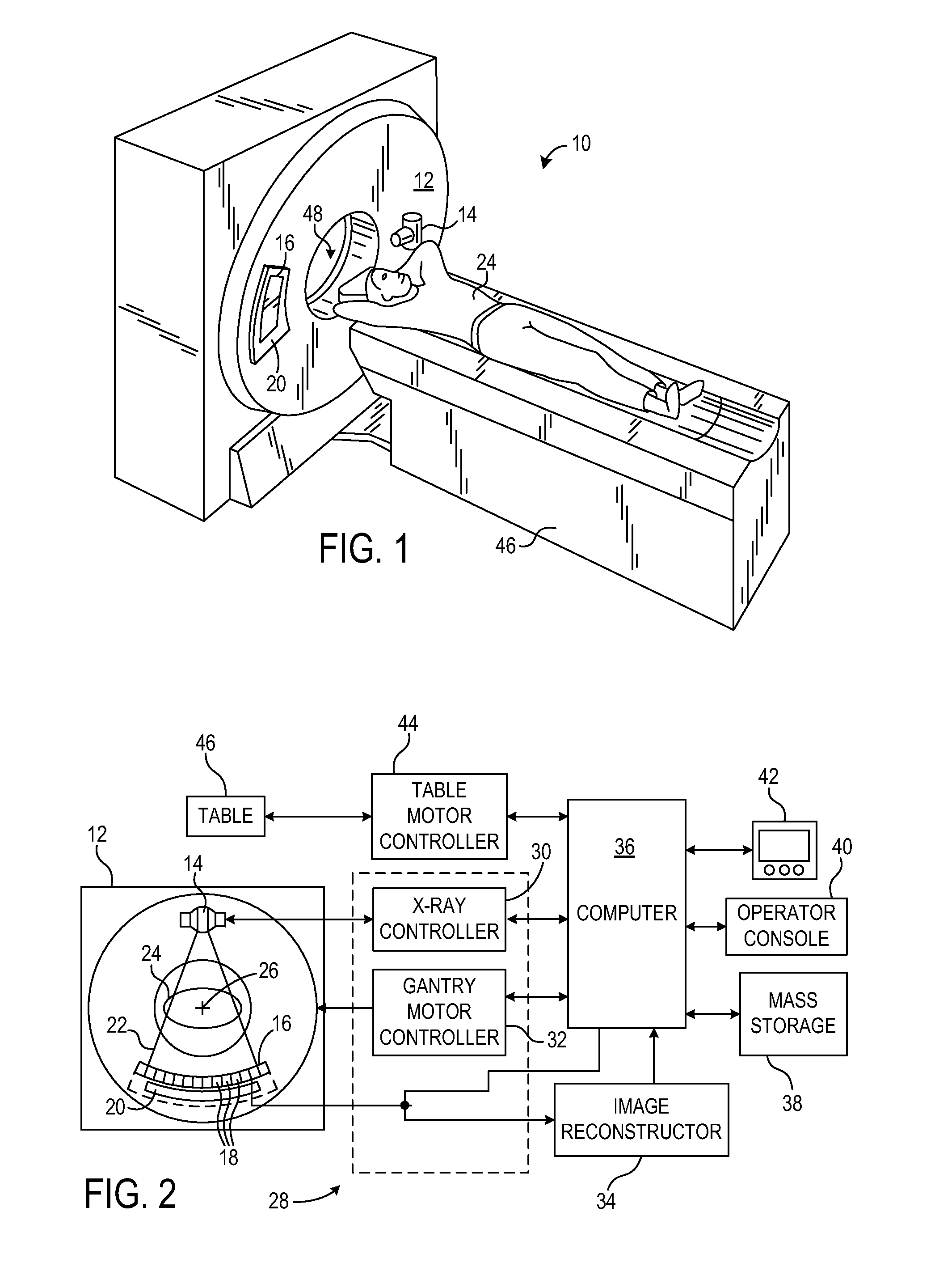
[0025]FIG. 1 is a block diagram of an embodiment of an imaging system 10 designed both to a...


PUM


Abstract

An x-ray tube assembly includes a vacuum enclosure that includes a cathode portion, a target portion, and a throat portion having a plurality of recesses formed therein to break up eddy currents generated in the throat portion. The throat portion has an upstream end coupled to the cathode portion and a downstream end coupled to the target portion. The x-ray tube assembly also includes a target positioned within the target portion of the vacuum enclosure, and a cathode positioned within the cathode portion of the vacuum enclosure. The cathode is configured to emit a stream of electrons through the throat portion toward the target.

Description

BACKGROUND OF THE INVENTION[0001]Embodiments of the invention relate generally to diagnostic imaging and, more particularly, to an apparatus and method for improved transient response in an electromagnetically controlled x-ray tube.[0002]X-ray systems typically include an x-ray tube, a detector, and a support structure for the x-ray tube and the detector. In operation, an imaging table, on which an object is positioned, is located between the x-ray tube and the detector. The x-ray tube typically emits radiation, such as x-rays, toward the object. The radiation typically passes through the object on the imaging table and impinges on the detector. As radiation passes through the object, internal structures of the object cause spatial variances in the radiation received at the detector. The detector then transmits data received, and the system translates the radiation variances into an image, which may be used to evaluate the internal structure of the object. One skilled in the art wil...

Claims


Application Information

Patent Timeline
Patent Type & Authority Patents(United States)
IPC IPC(8): H01J35/30
CPCH01J35/14H01J35/16H01J2235/1216H01J2235/16H01J35/147H01J35/153
Inventor ROGERS, CAREY SHAWNFRONTERA, MARK ALANWESTCOT, ETHAN JAMESZAVODSZKY, PETER ANDRAS
Owner GENERAL ELECTRIC CO
Learn More