Method, system, and apparatus for managing alarms in long-reach passive optical network system

a passive optical network and alarm technology, applied in the field of passive optical network technology, can solve the problems of increasing the complexity of fast failure locating, reducing the stability and reliability of the device in the system, and causing long-distance fiber failures to occur, so as to facilitate device maintenance

Inactive Publication Date: 2012-10-09
APEX NET LLC
View PDF17 Cites 8 Cited by
  • Summary
  • Abstract
  • Description
  • Claims
  • Application Information

AI Technical Summary

Benefits of technology

[0022]Through the method, system and apparatus disclosed herein, the alarm detection function is added in the E-R regenerator, and the detected alarm signal is transmitted to the OLT or ONU, so that the OLT can analyze, judge and locate the failure and can distinguish the alarm level, thus facilitating device maintenance. In this way, the LR-PON transmission quality is monitored, and various alarm indications in the LR-PON signal monitoring are processed properly.

Problems solved by technology

Although the E-R regenerator extends the coverage of the PON and enables the OLT to cover ONUs as far as required, long-distance fiber failures may arise after the fiber transmission distance is extended from 20 km to 100 km.
The active E-R device introduced into the PON also reduces the stability and reliability of the device in the system.
The E-R regenerator on the feed fiber divides the Fiber path into two sections, which increases the complexity of fast failure locating.
Previous alarm indications and maintenance functions are transmitted transparently, and the failures of the intermediate nodes cannot be analyzed or located.
Therefore, the existing E-R LR-PON solution does not monitor the LR-PON signals, and does not put forward various alarm indications raised in the LR-PON signal monitoring or the corresponding processing method.

Method used


Image

  • Method, system, and apparatus for managing alarms in long-reach passive optical network system
  • Method, system, and apparatus for managing alarms in long-reach passive optical network system
  • Method, system, and apparatus for managing alarms in long-reach passive optical network system

Examples


first embodiment

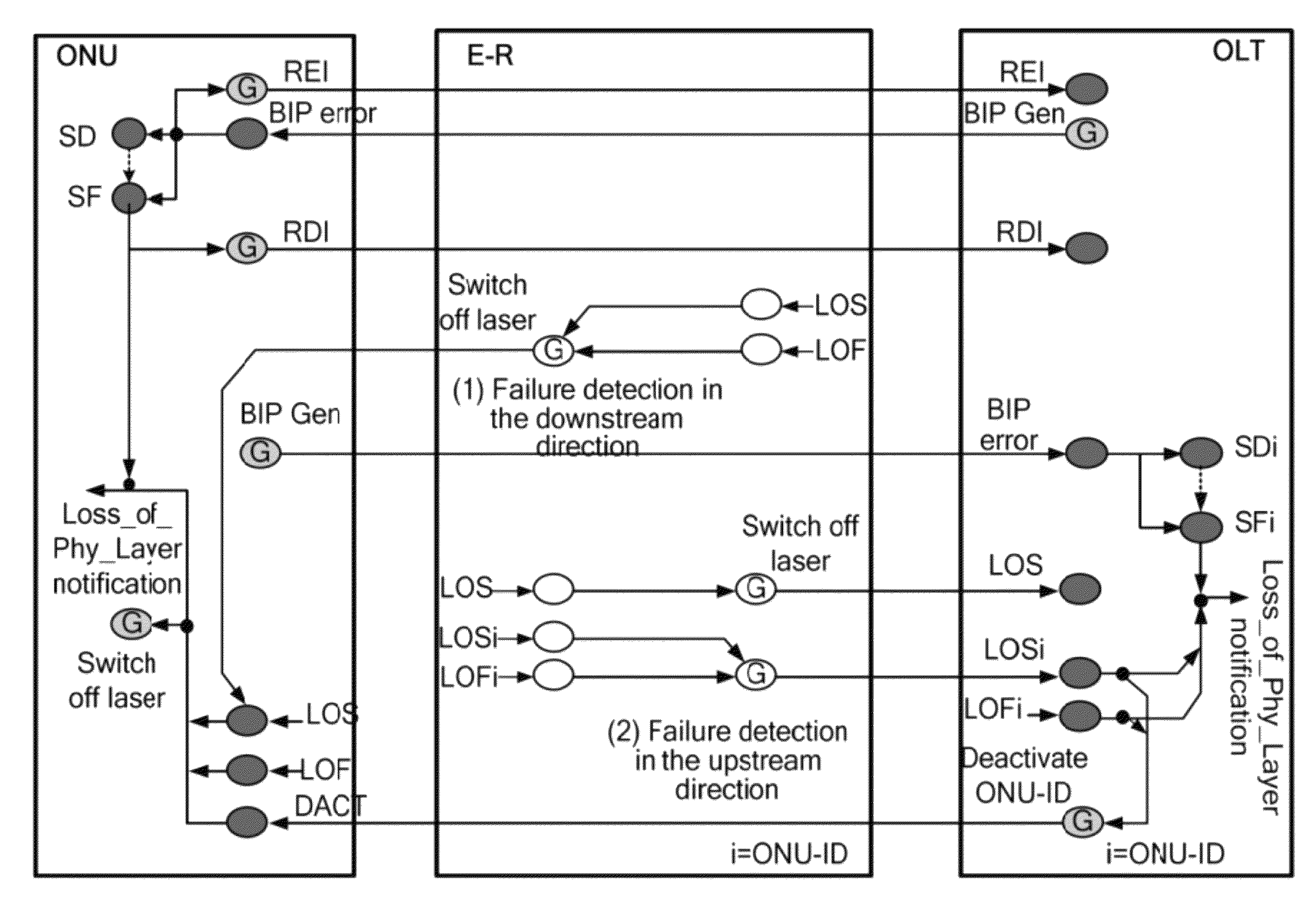
[0047]FIG. 4 shows alarm links according to the first embodiment of the present invention. In this embodiment, alarm detection functions are added only to the E-R generator, and the ONU and the OLT remain unchanged.

[0048]Downstream Direction:

[0049]After detecting an LOS or LOF alarm, the E-R regenerator switches off the transmitting laser in the downstream direction, so that the ONU detects the LOS alarm in the downstream direction. The subsequent processing is the same as that in the prior art; that is, the ONU determines that an LOS failure occurs on the downstream path from the E-R regenerator to the ONU. After knowing that the LOS alarm and the LOF alarm are cleared, the E-R regenerator switches on the transmitting laser in the downstream direction again.

[0050]Upstream Direction:

[0051]After detecting the LOS alarm, the E-R regenerator switches off the transmitting laser in the upstream direction, so that the OLT detects the LOS alarm in the upstream direction. The subsequent pro...

second embodiment

[0054]FIG. 5 shows alarm links according to the second embodiment of the present invention. The features that make this embodiment different from the first embodiment are as follows: An alarm back-transmission function is added to the E-R regenerator; the OLT can detect and process three additional types of alarms to facilitate failure judgment and locating; and the ONU remains unchanged.

[0055]Downstream Direction:

[0056]After detecting the LOS and LOF alarms, the E-R regenerator switches off the transmitting laser in the downstream direction, the details of which are the same as those of the first embodiment and are provided further.

[0057]After detecting the LOS and LOF alarms, the E-R regenerator sends the set third-type downstream Alarm Indication Signal (AIS) back to the OLT. Here the third-type downstream AIS is an RDIu alarm.

[0058]As shown in Table 1, after receiving the RDIu alarm, the OLT determines that a failure leading to LOS or LOF occurs on the downstream path from the O...

third embodiment

[0067]FIG. 7 shows alarm links according to the third embodiment of the present invention. The features that make this embodiment different from the second embodiment are as follows: One more alarm back-transmission function is added to the E-R regenerator, and the ONU can detect and process two additional types of alarms.

[0068]Downstream Direction:

[0069]After detecting the LOS and LOF alarms, the E-R regenerator does not switch off the transmitting laser in the downstream direction, but inserts the first-type downstream AIS to the ONU. The first-type downstream AIS is an AISd alarm.

[0070]After receiving the AISd alarm, the ONU determines that a failure leading to LOS or LOF occurs on the downstream path from the OLT to the E-R regenerator. As shown in Table 3, the ONU suppresses the LOF alarm.

[0071]In the foregoing step, the inserted AISd alarm is an “alarm frame”. Its frame header is similar to the pattern format of the downstream frame delimiter “PSync” of the GPON. A simple mode...


PUM


Abstract

A method, system and apparatus for managing alarms in a Long Reach Passive Optical Network (LR-PON) system are disclosed. The method includes: obtaining a PON signal from an Optical Line Terminal (OLT) or an Optical Network Unit (ONU) on one side; checking whether the obtained PON signal fails; and notifying the ONU or the OLT on the other side if the PON signal fails. The method, system and apparatus under the present invention monitor the LR-PON transmission quality and process various alarm indications raised in the LR-PON signal monitoring.

Description

CROSS-REFERENCE TO RELATED APPLICATIONS[0001]This application is a continuation of International Application No. PCT / CN2008 / 072461, filed on Sep. 23, 2008, which claims the benefit of Chinese Patent Application No. 200710163635.3, filed on Oct. 15, 2007, both of which are hereby incorporated by reference in their entireties.FIELD OF THE INVENTION[0002]The present invention relates to a Passive Optical Network (PON) technology, and in particular, to a method, system and apparatus for managing alarms in a Long-Reach PON (LR-PON) system.BACKGROUND OF THE INVENTION[0003]Currently, with the emergence of the services such as Video on Demand (VOD), High-Definition Television (HDTV) and online gaming, telecom users raise higher and higher requirements on network bandwidth. Driven by such requirements, the Fiber to the Home (FTTH) technology that ensures the “last mile” access network is developing rapidly, and especially, the PON technology is applied widely.[0004]FIG. 1 shows a structure o...

Claims


Application Information

Patent Timeline
Patent Type & Authority Patents(United States)
IPC IPC(8): H04B10/08H04B10/079H04B10/272
CPCH04B10/07953H04B10/272H04J3/14H04J3/1694H04L41/0677H04Q11/0067H04B2210/08H04Q2011/0081H04Q2011/0083
Inventor ZHOU, JIANLINZOU, SHIMIN
Owner APEX NET LLC
Why Eureka
Try Eureka