Rifle scope and aligning device

Inactive Publication Date: 2012-10-16
MATTHEWS NICHOLAS DAVID JOHN
View PDF25 Cites 23 Cited by
  • Summary
  • Abstract
  • Description
  • Claims
  • Application Information

AI Technical Summary

Benefits of technology

[0011]Advantageously, the aligning device is removably attached to a free end of the ocular. Preferably, the aligning device comprises a ring that carries the markings and is mounted on the free end of the ocular.

Problems solved by technology

Parallax error causes the image of the target to move in relation to the cross hairs viewed through the scope, thus affecting accuracy.
If the shooter misjudges this, inaccuracy can result.
The axial spacing of the two reticles is relatively small, which makes it difficult to see small misalignments.
Because the reticles are both mounted internally and seen only in silhouette, they

Method used


Image

  • Rifle scope and aligning device
  • Rifle scope and aligning device
  • Rifle scope and aligning device

Examples


first embodiment

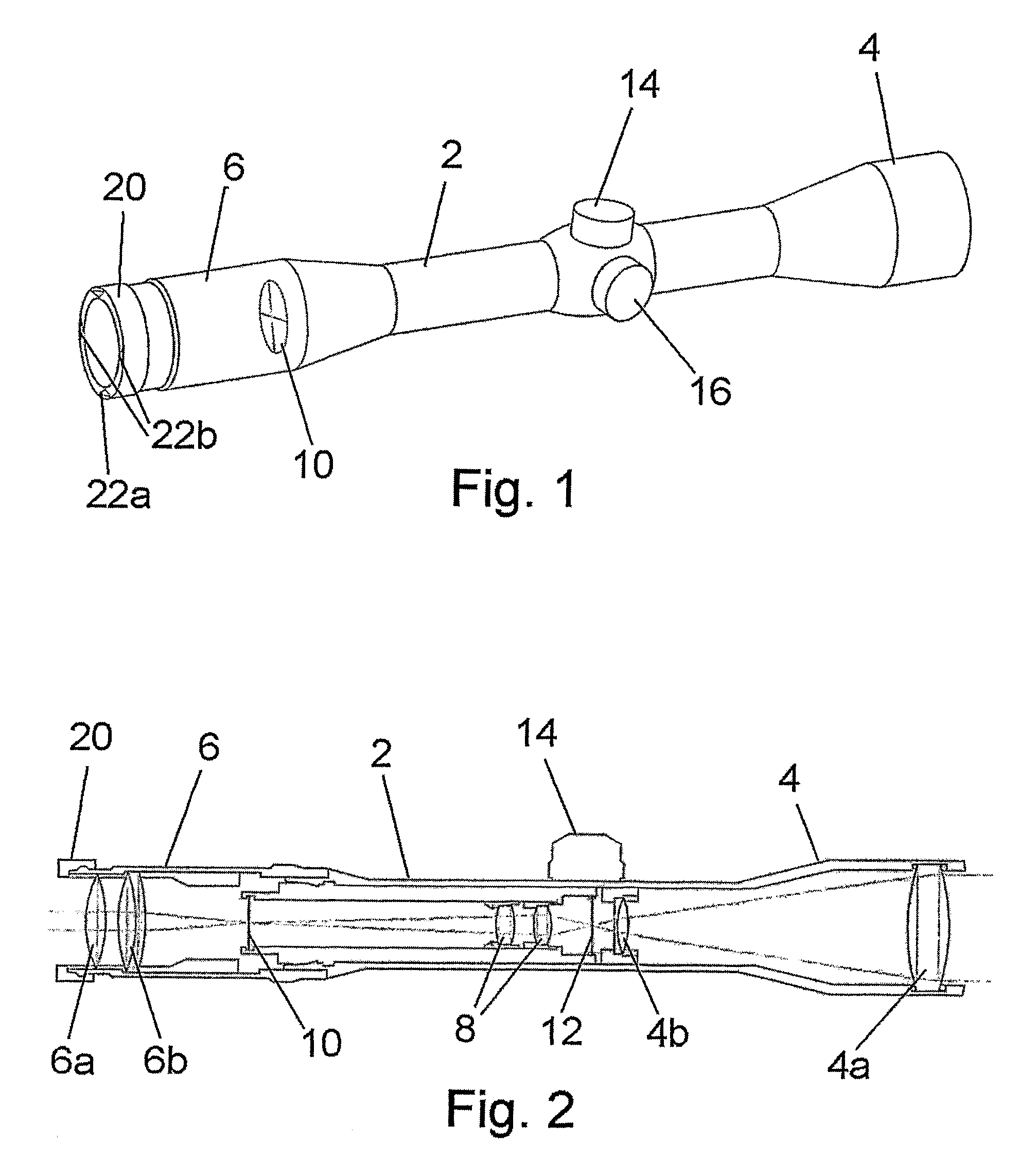
[0028]FIGS. 1 and 2 show a rifle scope according to the invention. The rifle scope includes a cylindrical body 2 having an objective 4 at one end and an ocular 6 (or eye piece) at the opposite end. In the embodiment, the objective 4 includes two sets of objective lenses 4a,4b and the ocular 6 includes two sets of ocular lenses 6a,6b. Between the objective and the ocular, the scope includes a set of erector lenses 8.

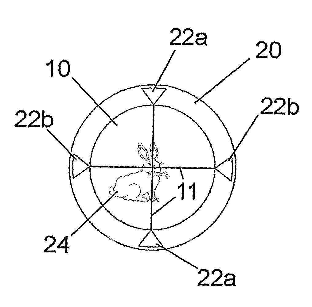
[0029]The scope includes a reticle 10, for example a pair of cross hairs 11, which the shooter uses for aiming. In the embodiment, the reticle 10 is located in the focal plane of the ocular 6, which is the preferred position for hunting. Alternatively, the reticle may be placed in the objective focal plane 12, this being the preferred position for tactical (military) uses. The scope includes an elevation turret 14 and windage turret 16, which are used for adjusting the vertical and horizontal positions of the reticle.

[0030]All the features described above are entirely con...

second embodiment

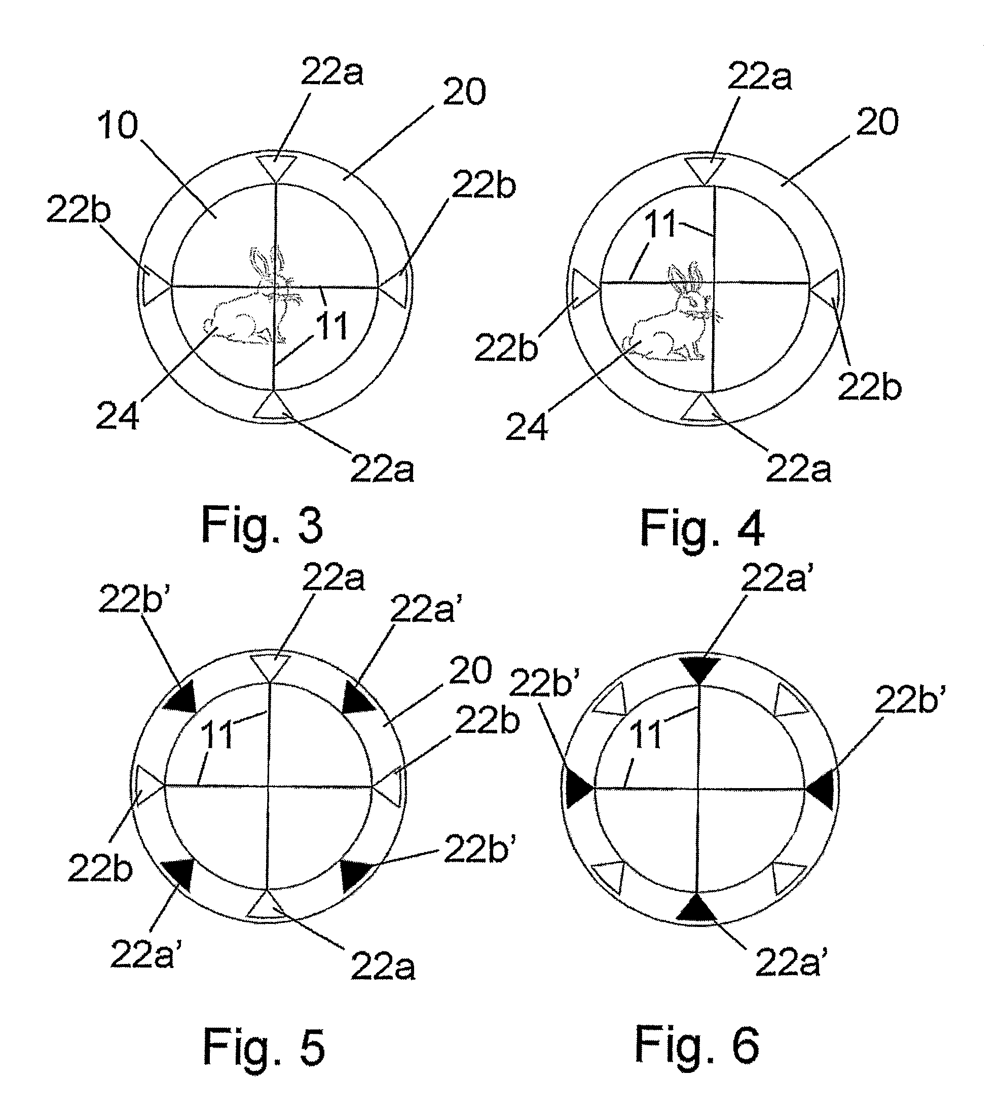
[0036]FIGS. 5 and 6 illustrate the invention, in which the ring 20 carries two separate sets of quadrant markings 22a,22b and 22′a, 22′b. The ring 20 can be rotated counter-clockwise from the position shown in FIG. 5 through an angle of 45° to the position shown in FIG. 6. When the ring is in the position shown in FIG. 5, eye alignment is checked using the first set of quadrant markings 22a,22b, and when the ring is rotated to the second position shown in FIG. 6, eye alignment is checked using the second set of quadrant markings 22′a, 22′b.

[0037]The two sets of markings 22a,22b and 22′a, 22′b have different visibilities and are designed for use under different light conditions. For example, the first set of markings 22a,22b may be coloured white for use in low light conditions, and the second set of markings 22′a, 22′b may be coloured black for use under bright light conditions. Other colours may of course be used, or one or both sets of markings may be reflective, fluorescent or i...


PUM


Abstract

A rifle scope includes an ocular (6), an objective (4), a reticle (10) and an aligning device (20) that is displaced axially from the reticle and includes one or more markings (22a, 22b) that are visible in use to a shooter. The aligning device (20) is constructed and arranged such that with correct eye alignment the markings (22a, 22b) appear to be aligned with the reticle (10), and with incorrect eye alignment the markings appear to be misaligned with the reticle.

Description

RELATED APPLICATIONS[0001]This application is the U.S. National Phase filing under 35 U.S.C. §371 of PCT / GB2006 / 004664, filed Dec. 13, 2006, which designated the United States and was published in English, which claims priority under 35 U.S.C. §119 (a)-(d) to Great Britain Patent Application No. 0525983.3, filed Dec. 21, 2005. The contents of these applications is incorporated herein by reference in their entireties.FIELD OF THE INVENTION[0002]The present invention relates to a rifle scope: that is, a telescopic sight for rifles and other guns. The invention also relates to an aligning device for use with a rifle scope, to ensure correct eye alignment and prevent parallax error, so improving the accuracy of shooting.BACKGROUND OF THE INVENTION[0003]Accurate and consistent shooting requires central eye alignment through a rifle scope to prevent parallax error. Parallax error causes the image of the target to move in relation to the cross hairs viewed through the scope, thus affecting...

Claims


Application Information

Patent Timeline
IPC IPC(8): F41G1/38
CPCF41G1/38G02B23/14G02B23/00
Inventor MATTHEWS, NICHOLAS DAVID JOHN
Owner MATTHEWS NICHOLAS DAVID JOHN
Why Eureka
Try Eureka