
Archery sight with correlated distance indicators

Active Publication Date: 2015-02-24
SCHAEFER BENJAMIN P
View PDF14 Cites 2 Cited by
  • Summary
  • Abstract
  • Description
  • Claims
  • Application Information

AI Technical Summary

Benefits of technology

The present invention relates to a device that allows an archer to preset a sight for a specific bow and arrow combination. It also allows the archer to set markers at specific distances and ensures that each marker is uniquely identified by a corresponding pin. The device helps in easy and quick identification of the correlated sight pins and markers. Additionally, it facilitates range finding without requiring additional apparatus or movement. Overall, the device provides a cost-effective and user-friendly solution for enabling young and infrequent archers to improve their skills.

Problems solved by technology

As may be appreciated, these fletchings are often fragile, and in many cases easily damaged or even stripped from the shaft if handled roughly.
One of the challenges that arise from the diverse equipment used in modern archery is how to enable an archer to account for the many variables, and still reliably and accurately shoot the arrow.
For a highly skilled archer, this may be second nature, but in the heat of the moment, even the most skilled and practiced archers can momentarily become confused about the particular pin to be used at a particular distance.
Nevertheless, and in spite of the advantages of the Logsdon sight, there remain several drawbacks.
Among these is the cost, requiring the archer to buy a computer-controlled sight and compatible laser rangefinder.
Furthermore, a laser-controlled range finder and computer controlled sight each require batteries, which are well known to lose charge at the most inopportune moments.
The incorporation of electronics also makes the apparatus far more susceptible to the environment and far more likely to fail.
Unfortunately, with the excitement of the animal approaching, there still remain a significant number of archers who may temporarily be overwhelmed, and not select the proper adjacent pin.
This is particularly true for younger and less frequent archers, both for whom the cost of the Logsdon sight is also more difficult to justify.

Method used


Image

  • Archery sight with correlated distance indicators
  • Archery sight with correlated distance indicators
  • Archery sight with correlated distance indicators

Examples


Embodiment Construction

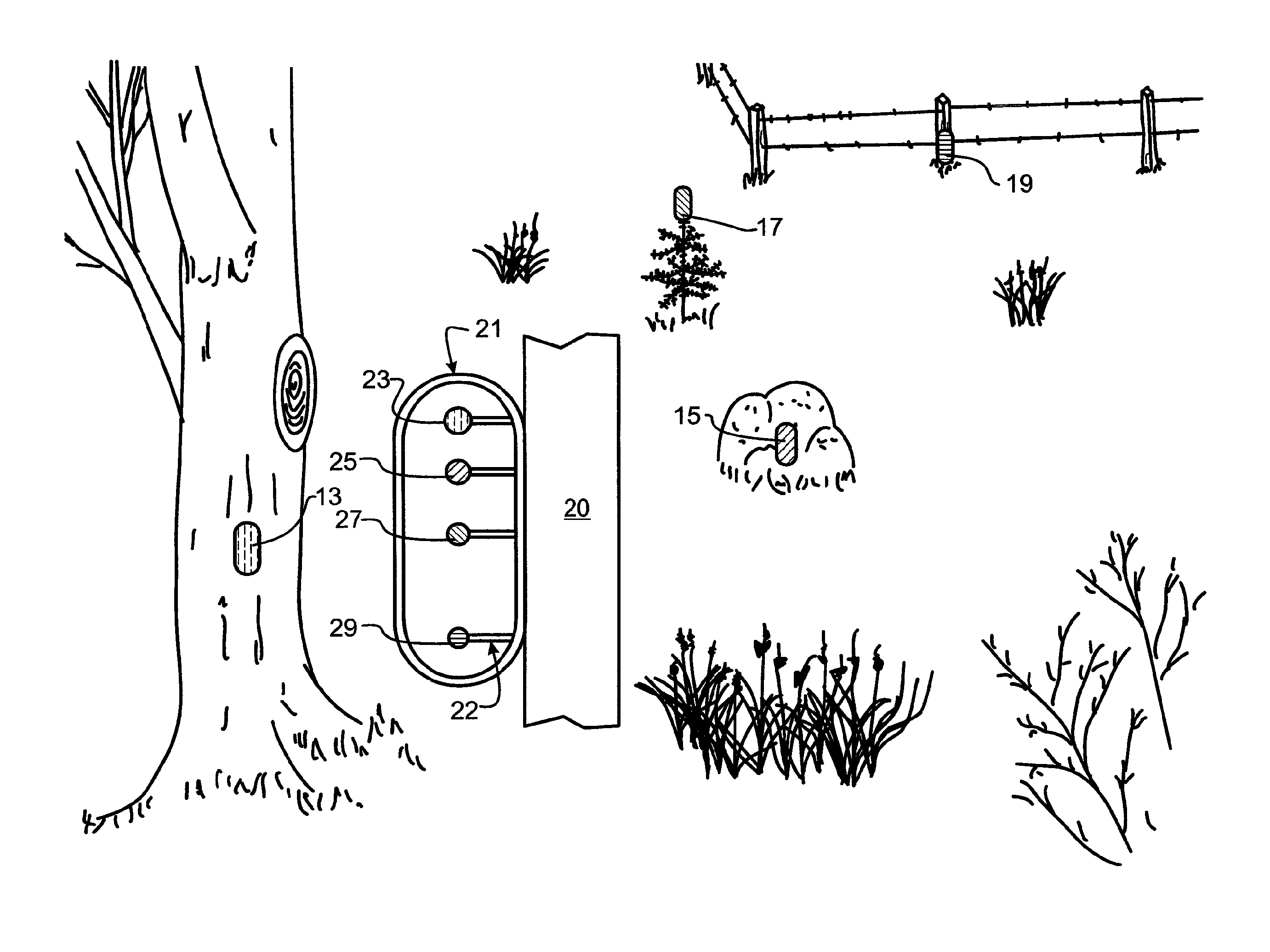
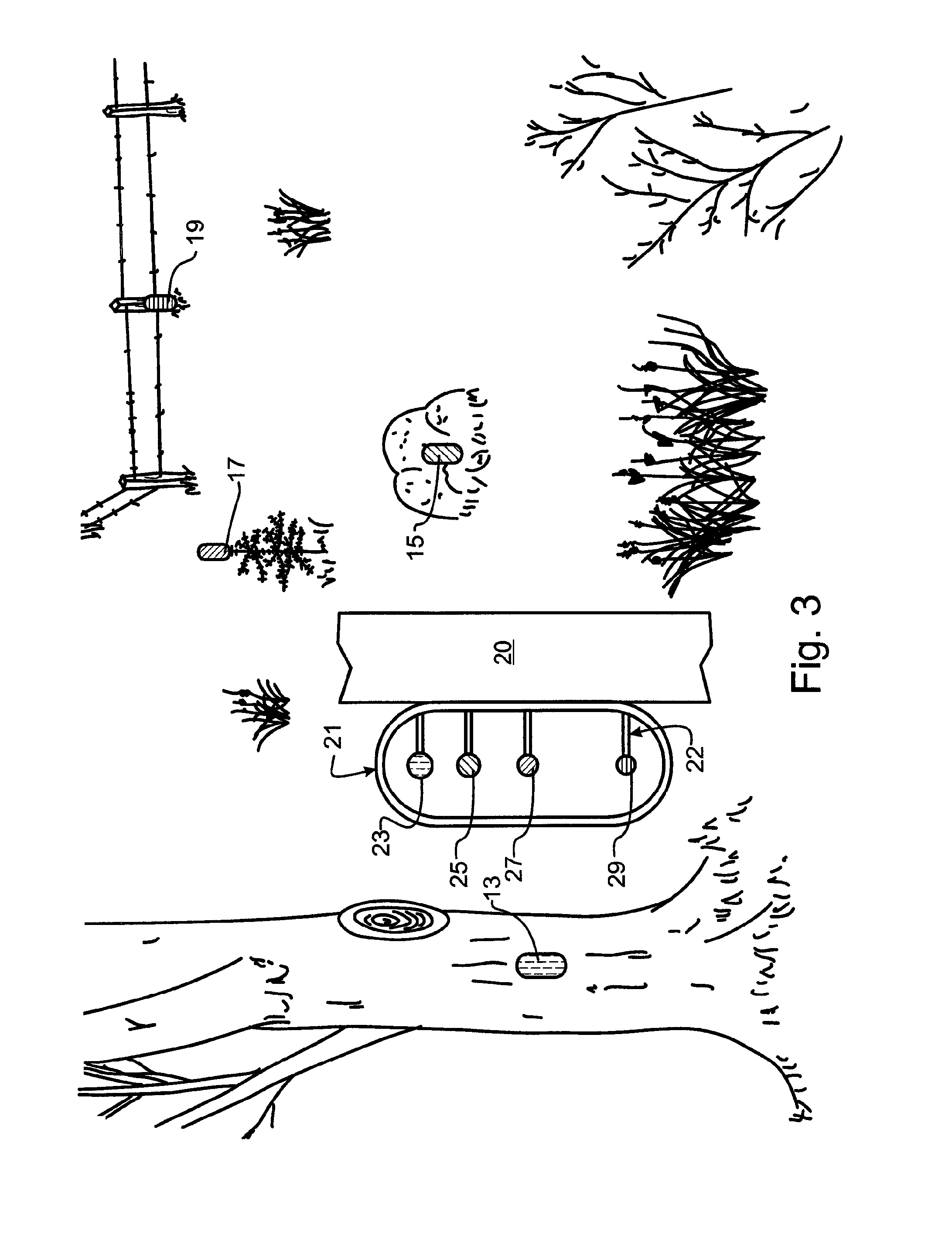
[0019]Manifested in the preferred embodiment, the present invention provides markers using consistent indicia uniquely associated with particular discrete distances; and correlation between sight distance indicia and marker distance indicia. As illustrated in FIG. 3, preferred embodiment archery sight 21 may be mounted on a suitable bow 20 in the standard way. As illustrated, sight 21 includes four pins 22, though this is simply for illustrative purposes, and in fact sight 21 may include any number of pins as may be desired or appropriate for a particular archer, bow and arrow combination.

[0020]Each pin 22 will preferably have a head having a unique indicia or characteristic. In the preferred embodiment, the indicia or characteristic is color. As illustrated, pin head 23 is violet, pin head 25 is brown, pin head 27 is green, and pin head 29 is blue. Correlated with pin heads 23-29 are distance markers 13-19. Marker 13 for exemplary purposes might indicate a 10 yard distance, and is ...


PUM


Abstract

A hunting sight has a plurality of pins that each have a head having a unique characteristic such as a color or shape. Each pin head is sighted for a particular discrete distance from the sight to a target. A plurality of markers are anchored in arcs at discrete predetermined radial distances from a hunting location such as a hunting stand or hunting blind. Each of the markers have a characteristic such as a color or shape that matches the unique characteristic of the pin head that corresponds to the distance between the sight and marker. A method of correlating the archery sight with distance indicators, and of using the archery sight with correlated distance indicators, is also disclosed.

Description

BACKGROUND OF THE INVENTION[0001]1. Field of the Invention[0002]This invention pertains generally to archery, and more particularly to an archery sight having correlated distance indicators.[0003]2. Description of the Related Art[0004]The modern sport of archery has evolved greatly from the earliest days of recorded history. Ancient archers used the bow and arrow as a tool for survival, for gathering food and for protection. Through the centuries, there have been many technological and social advances. While the bow and arrow are still useful for basic survival functions, most modern archers are hunting, practicing with targets, or otherwise enjoying the sport.[0005]The equipment used by modern archers is also much different than that of the earliest hunters. Today, bows range from simple bent or stretched sticks made in the traditions of the earliest hunters to the recurve and cross bows that were developed as humans gained skill in woodworking, to the ultra-modern compound bows of...

Claims


Application Information

Patent Timeline
IPC IPC(8): F41G1/467
CPCF41G1/467F41G1/473
Inventor SCHAEFER, BENJAMIN P.
Owner SCHAEFER BENJAMIN P
Learn More