Microfluidic system and method for creating an encapsulated droplet with a removable shell

a microfluidic system and droplet technology, applied in the field of encapsulated droplets, can solve the problems of increasing system costs or limiting the applicable situations and environments, difficulty in manually dispensing of oil-shells with controlled and reproducible volumes, and consequently affecting evaporation, etc., to achieve the effect of high predictability and repeatability, and easy removal

Inactive Publication Date: 2012-10-16
NAT CHIAO TUNG UNIV
View PDF3 Cites 5 Cited by
  • Summary
  • Abstract
  • Description
  • Claims
  • Application Information

AI Technical Summary

Benefits of technology

[0013]1. Each volume of the shell droplet and the core droplet can be determined by the size of the first channel electrode and the distance between the first and second electrode plates, so that the volume thereof can be precisely calculated and experimentally obtained with high predictability and repeatability.
[0014]2. The shell droplet of the encapsulated droplet can be easily removed by merging it with the removing liquid.

Problems solved by technology

The rapid evaporation is consequently an issue to the shrunk droplets.
However, the straight forward solutions may increase the systems cost or limit the applicable situations and environments.
However, making the oil-shell with a controlled and reproducible volume by manually dispensing is difficult.

Method used


Image

  • Microfluidic system and method for creating an encapsulated droplet with a removable shell
  • Microfluidic system and method for creating an encapsulated droplet with a removable shell
  • Microfluidic system and method for creating an encapsulated droplet with a removable shell

Examples


Embodiment Construction

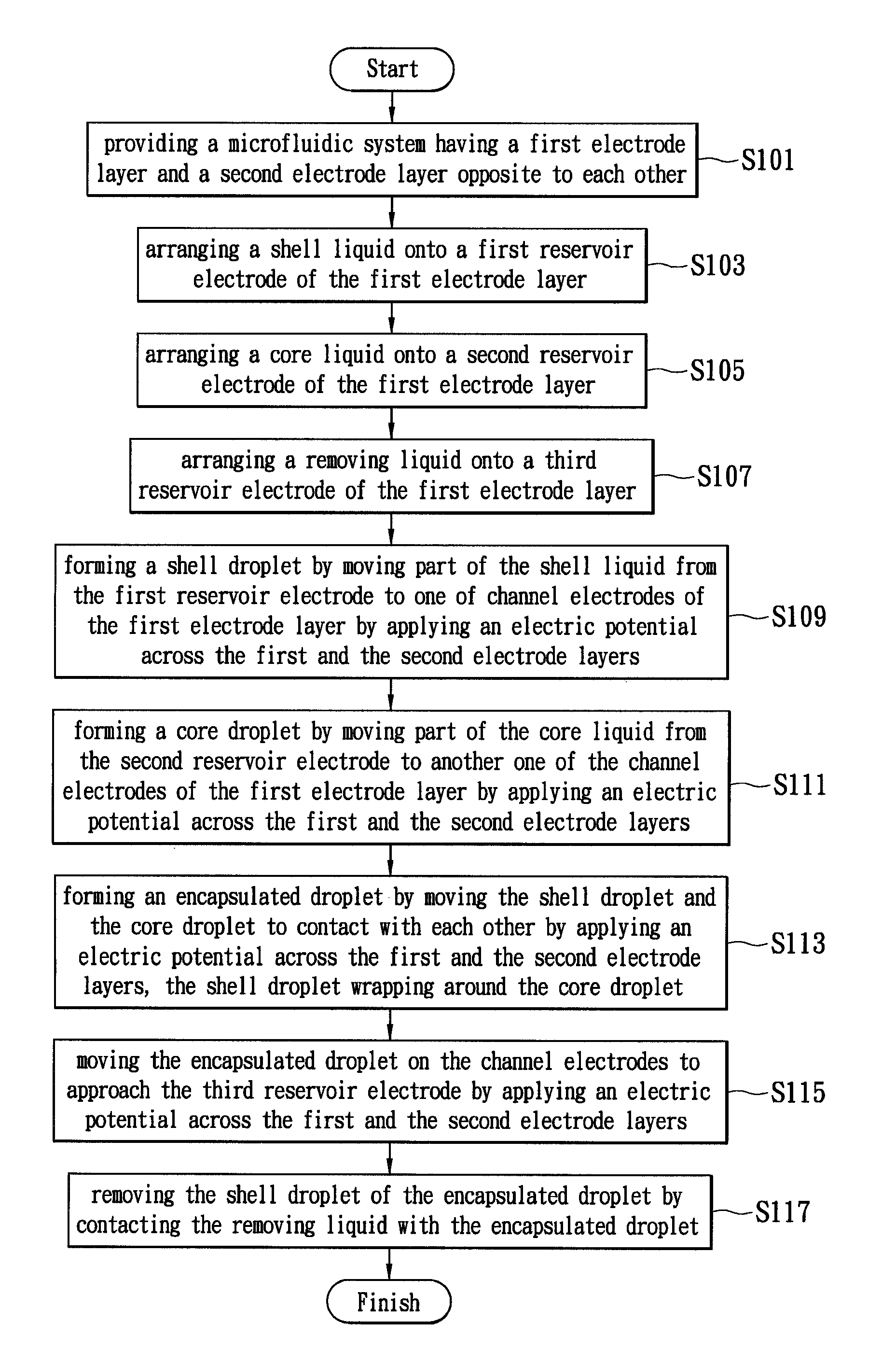
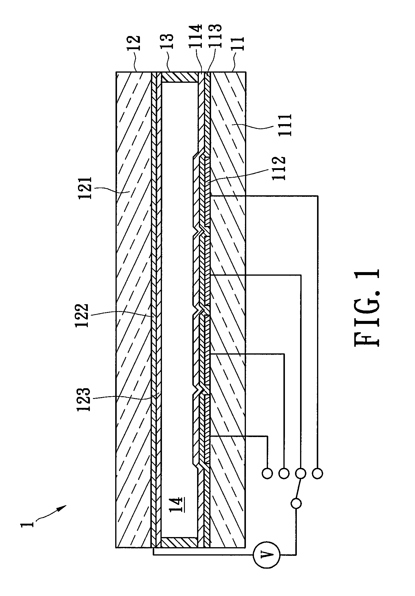
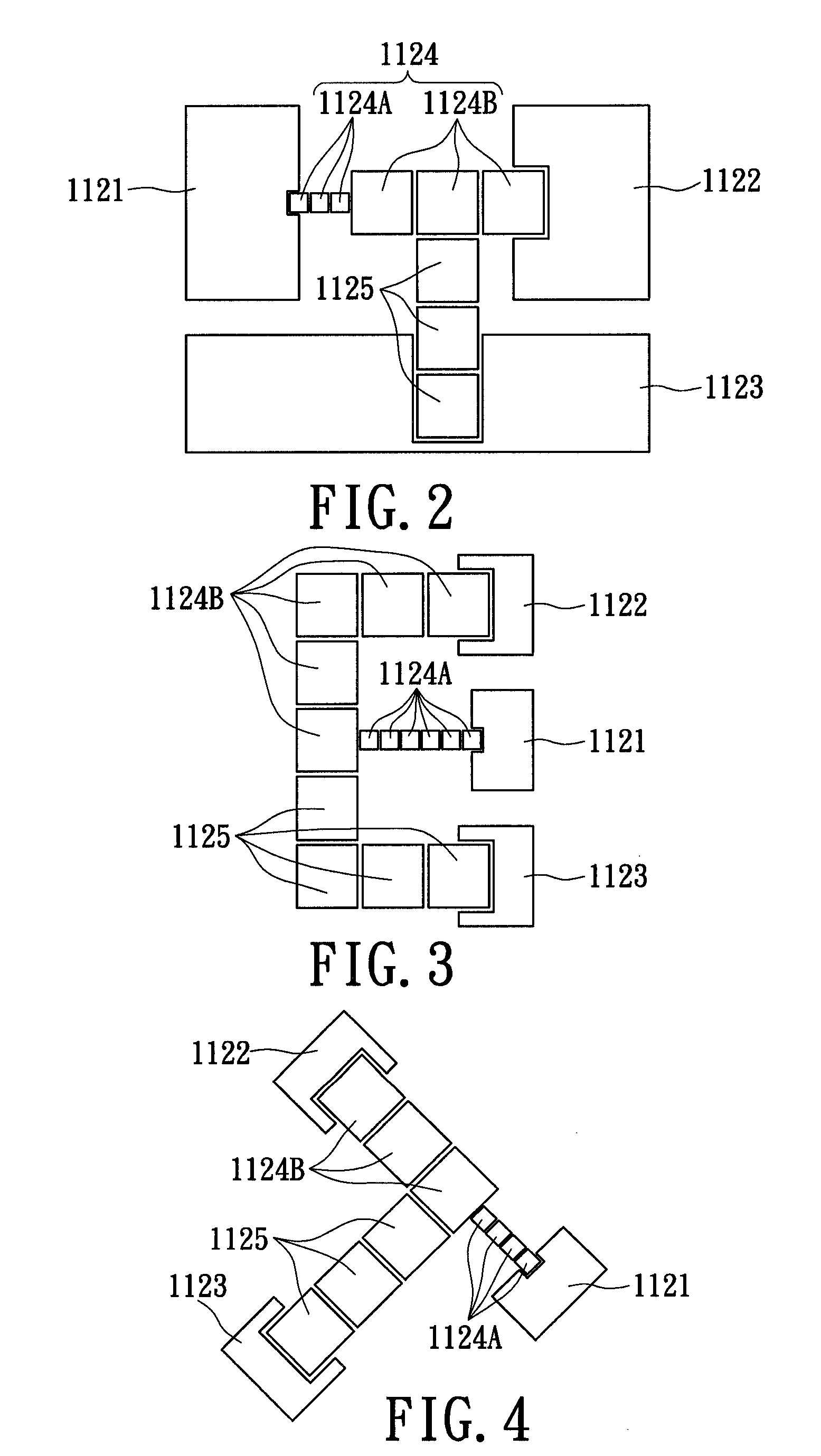
[0026]Referring now to FIGS. 1 and 2, in which a microfluidic system for creating an encapsulated droplet with a removable shell in accordance with a preferred embodiment of the present invention is disclosed. For conciseness of illustration, the “microfluidic system for creating an encapsulated droplet with a removable shell” is called “microfluidic system” for short. The microfluidic system 1 includes a first electrode plate 11, a second electrode plate 12, and a spacing structure 13. After detailed descriptions for the technical feature of the microfluidic system 1, method for using the microfluidic system 1 will be introduced thereby.

[0027]The first electrode plate 11 includes a first substrate 111, a first electrode layer 112, a dielectric layer 113 and a first hydrophobic layer 114.

[0028]The first substrate 111 can be a rectangular substrate, which is made of glass materials, silicon materials, poly-dimethylsiloxane (PDMS), polyethylene terephthalate (PET), polyethylene naphth...


PUM

PropertyMeasurementUnit
dielectric constantaaaaaaaaaa
electric potentialaaaaaaaaaa
conductiveaaaaaaaaaa

Abstract

A microfluidic system for creating encapsulated droplets whose shells can be further removed comprises: two electrode plates and a spacing structure disposed between the two electrode plates. One of the electrode plates has three reservoir electrodes and a plurality of channel electrodes. The three electrodes are respectively used for accommodating a shell liquid, a core liquid, and a removing liquid which is able to remove the shell liquid. The channel electrodes are used for communicating droplets among the three reservoir electrodes. Via these arrangements, the microfluidic system can create a quantitative shell droplet and a quantitative core droplet, and then merge the shell and core droplets to form an encapsulated droplet. Moreover, the shell of the encapsulated droplet can be removed by mixing it with the removing liquid. This invention is further provided with a method for creating an encapsulated droplet with a removable shell.

Description

BACKGROUND OF THE INVENTION[0001]1. Field of the Invention[0002]The present invention relates to an encapsulated droplet, in particular, to a microfluidic system and a method for creating an encapsulated droplet with a removable shell.[0003]2. Description of Related Art[0004]The microfluidic system, which is also called the microfluidic chip, now is widely studied and highly valued. It has many advantages, such as, high response rate, high sensitivity, high reproducibility, low cost, and low pollution, so as to be applied to biology, medicine, optoelectronics and other fields.[0005]For the latest technology of the droplet-based microfluidic system, the volume of the driven droplet has been decreased to the level of sub-micro liter, or even to the level of pico liter. The rapid evaporation is consequently an issue to the shrunk droplets.[0006]Then, possible solutions to this rapid-evaporation issue include enhancement of packaging and sealing of the microfluidic system or precise con...

Claims


Application Information

Patent Timeline
Patent Type & Authority Patents(United States)
IPC IPC(8): B01D57/02C25B7/00G01L9/18G01L1/20G01F1/64C25B15/00C08F2/58C07K1/26C02F1/469B01D59/50B01D59/42
CPCB01J13/04Y10T436/2575
Inventor FAN, SHIH-KANGHSU, YAO-WENCHEN, CHIUN-HSUN
Owner NAT CHIAO TUNG UNIV
Why Eureka
Try Eureka