Pulley tensioner for an oil wet belt drive

Inactive Publication Date: 2012-10-23
DAYCO EURO
View PDF49 Cites 15 Cited by
  • Summary
  • Abstract
  • Description
  • Claims
  • Application Information

AI Technical Summary

Problems solved by technology

However, a compartment designed for accommodating a chain drive presents an internal space which imposes major restrictions to the dimensions of an automatic pulley tensioner both along the axial direction and along the radial direction.

Method used


Image

  • Pulley tensioner for an oil wet belt drive
  • Pulley tensioner for an oil wet belt drive

Examples


Embodiment Construction

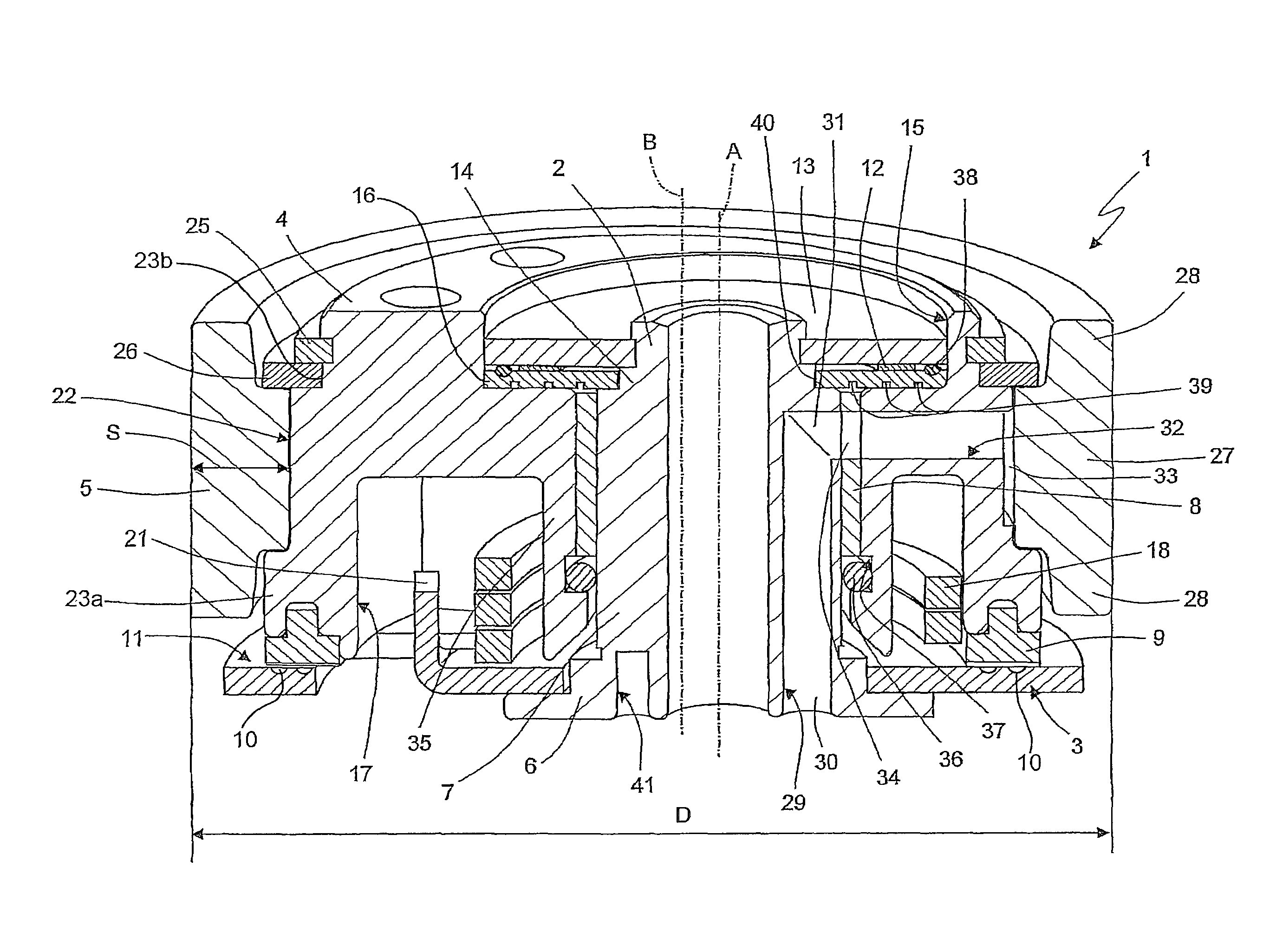
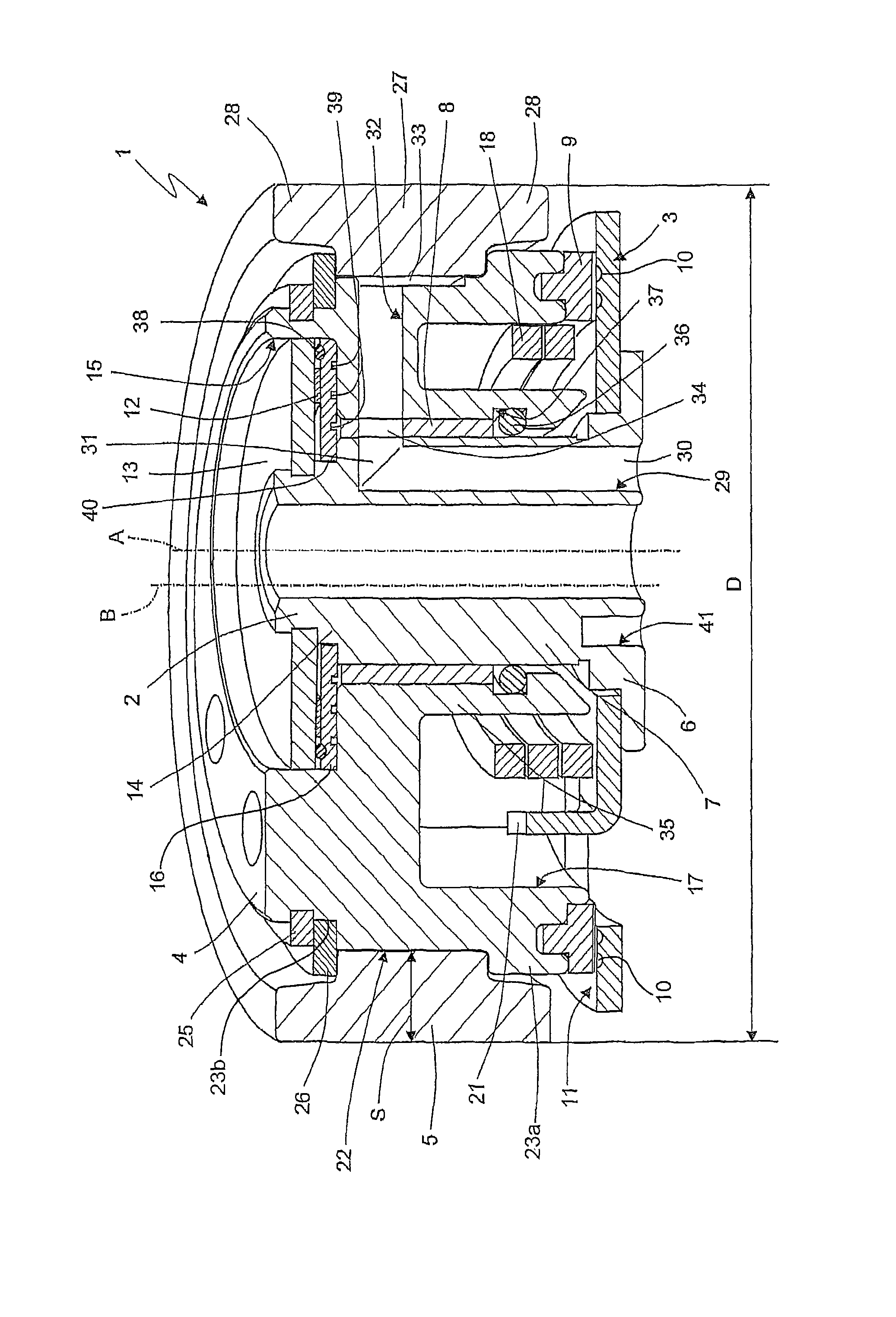
[0013]With reference to the FIGURE, numeral 1 indicates as a whole a pulley tensioner for a timing belt drive comprising a pivot 2 defining an axis A and a plate 3 perpendicular to axis A and mounted rigidly to pivot 2 so as to form a rigid base adapted to be removably connected to a wall of an internal combustion engine. Tensioner 1 further comprises an eccentric arm 4 mounted on pivot 2 and an annular pulley 5 concentrically mounted on eccentric arm 4 and rotatable about an axis B parallel to and distanced from axis A.

[0014]Specifically, pivot 2 integrally defines an end portion 6 rigidly connected to plate 3 and a cylindrical portion 7 defining axis A for guiding the rotation of eccentric arm 4.

[0015]Eccentric arm 4 is radially supported on cylindrical portion 7 by a bushing 8 and rests in axial direction on plate 3 by means of a friction ring 9 formed by polyamide 4.6 and having a reversed T section for coupling with a seat corresponding to the eccentric arm 4.

[0016]Friction rin...


PUM


Abstract

A tensioner (1) for a belt drive comprises a base(2, 3) defining an axis (A), a mobile element (4) hinged onto axis (A) and defining a guiding surface (22), an elastic helical element (18) having a square or rectangular cross section for actuating the mobile element (4) and an idle pulley (5) surrounding the guiding surface (22). The tensioner (1) further comprises a journal bearing (4, 29, 32, 33) for supporting the pulley (5) on the guiding surface (22).

Description

TECHNICAL FIELD[0001]The present invention relates to a pulley tensioner for an oil wet belt drive, for example for a timing drive of an internal combustion engine.BACKGROUND ART[0002]Timing drives generally comprise either an oil-lubricated chain mounted in a compartment connected to the engine oil circuit or a dry-running toothed belt. A timing drive has recently been manufactured wherein either the belt is at least partially dipped in oil at rest, or the oil is adducted on the belt, e.g. by spraying by means of a specific nozzle or by whipping due to the action of the belt and of the pulleys.[0003]An oil wet belt drive is lighter and causes less vibrations than a chain drive. Furthermore, the belt of an oil wet belt drive requires a lower operating tension than that of a chain and experimental tests have demonstrated that such drive allows to considerably reduce fuel consumptions and carbon dioxide emissions with respect to a traditional chain drive.[0004]Such advantages may now ...

Claims


Application Information

Patent Timeline
Patent Type & Authority Patents(United States)
IPC IPC(8): F16H7/08F16H7/10F16H7/14F01M1/00
CPCF16H7/1245F16H7/1281F16H2007/081F16H7/12F16H7/14
Inventor ROLANDO, ADRIANOPANE, GIANLUCA
Owner DAYCO EURO
Why Eureka
Try Eureka