Fuel tank mounting device and an industrial use vehicle therewith

a technology for mounting devices and fuel tanks, which is applied in the direction of machine supports, transportation items, building scaffolds, etc., can solve the problems of ensuring the look-behind ease, spoiled look-behind ease, and complicated replacement work, so as to achieve satisfactory workability and enhance the look-behind ease of the operator

Active Publication Date: 2012-10-30
NIPPON YUSOKI
View PDF13 Cites 3 Cited by
  • Summary
  • Abstract
  • Description
  • Claims
  • Application Information

AI Technical Summary

Benefits of technology

[0012]In view of the above-described problems in the conventional technologies and anticipated solutions thereof, the present disclosure aims at providing a fuel tank mounting (and dismounting) device and an industrial use vehicle therewith, whereby the look-behind easiness of the operator can be enhanced; the fuel tank replacement work can be performed with one touch operation; the fuel tank can be hung-down to a lower (hung-down) home position near to the ground; and the satisfactory workability as to the tank replacement operation can be achieved.

Problems solved by technology

In this way, there has been a problem in ensuring the look-behind easiness.
Especially in a case where the fuel tank is made slide backward and the tank fixing means for fixing the fuel tank is placed on the counterweight of the vehicle rear side so as to reduce the slide distance, the look-behind easiness is further spoiled.
According to the device disclosed by the patent reference 1, the look-behind easiness can be improved to some extent; however, since the tank replacement work includes the steps of making the tank slide backward, rotating the tank and the supporting bracket thereof about an horizontal axis, and placing the tank in an upright attitude, the replacement work is complicated.
Further, since the device itself for performing this replacement work becomes complicated and the replacement work of heavy tanks has to be often performed, there is apprehension about problems.
In addition, for the conventional fuel tank dismounting device whereby the fuel tank is made slide toward the rear side direction when being dismounted for the replacement, the weight of the counterweight must be taken into consideration; namely, the counterweight needs to be weighty.
Therefore, in the conventional fuel tank mounting / dismounting device, there has been a difficulty that the slide distance is lengthy, the tank replacement workability is spoiled, and the mounting / dismounting device itself becomes large.
Moreover, in the conventional fuel tank dismounting device whereby the fuel tank is hung down by a rotation mechanism in an upright attitude after being made slide toward the rear side direction, there has been a difficulty in dismounting / mounting the fuel tank in / from the upright attitude, since there is a large space between the bottom face of the fuel tank and the ground, when the tank with the bracket is placed in the upright attitude.
On the other hand, as is often the case with a conventional industrial use vehicle, the seat for the operator needs to be made slide forward or the back of the seat needs to be reclined when the cover of the engine for the vehicle has to be opened so that the maintenance work as to the engine is performed; nevertheless, the counterweight of the conventional vehicle hinders this engine maintenance work.
Thus, there has been a problem that the maintenance work requires much expense in time and effort.

Method used


Image

  • Fuel tank mounting device and an industrial use vehicle therewith
  • Fuel tank mounting device and an industrial use vehicle therewith
  • Fuel tank mounting device and an industrial use vehicle therewith

Examples


Embodiment Construction

[0068]Hereafter, the present invention will be described in detail with reference to the embodiments shown in the figures. However, the dimensions, materials, shape, the relative placement and so on of a component described in these embodiments shall not be construed as limiting the scope of the invention thereto, unless especially specific mention is made.

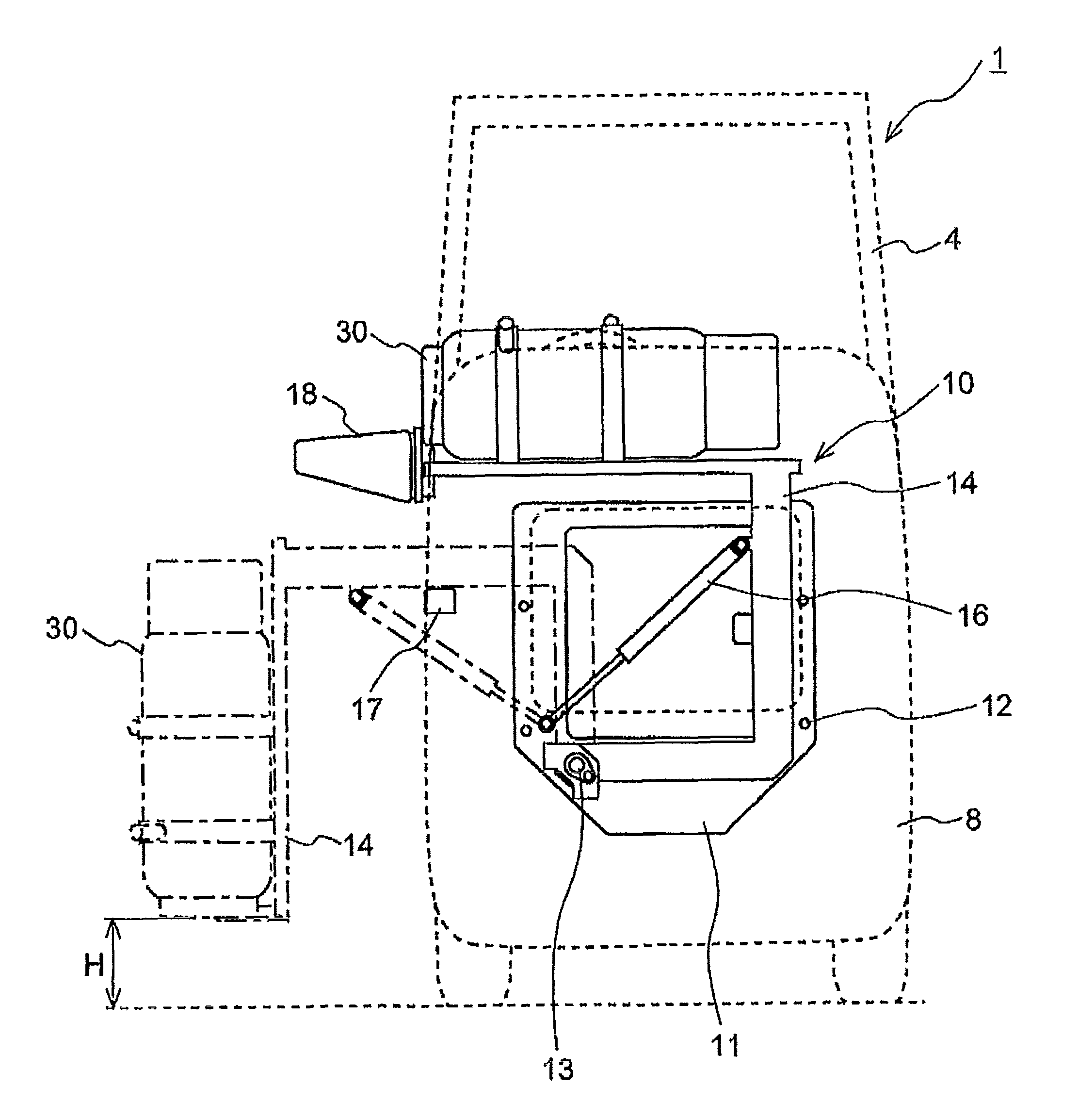
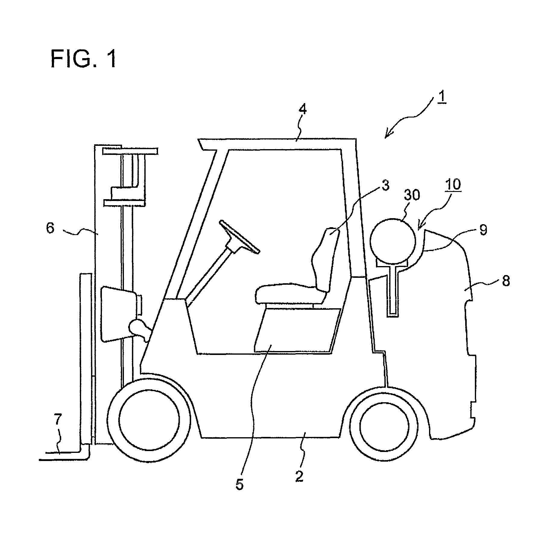
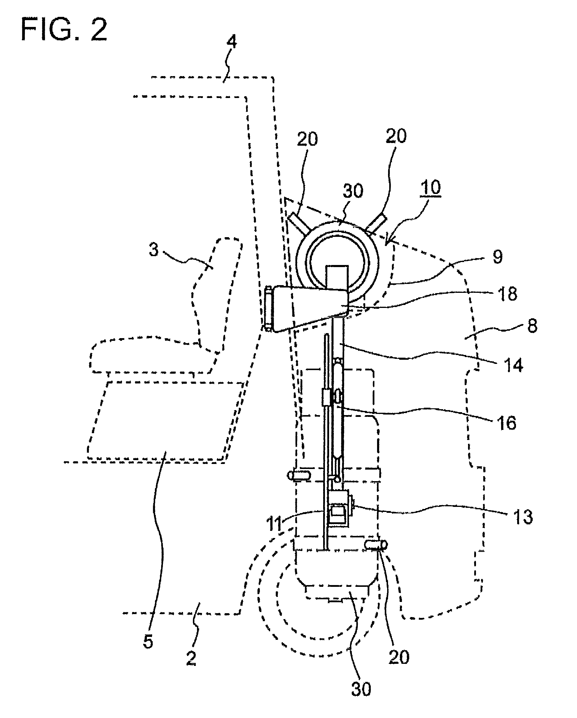
[0069]FIG. 1 shows a side view of a forklift that comprises a fuel tank mounting device according to an embodiment of the present invention; FIGS. 2-5 show various kind of views as to the fuel tank mounting device according to the embodiment of the present invention; FIG. 6 explains the look-behind easiness as to the forklift; FIG. 7a explains the opening operation as to the engine cover, according to the embodiment of the present invention; FIG. 7b explains the opening operation as to the engine cover, according to a conventional manner. In the embodiment according to the present invention, an explanation with an example of a for...


PUM


Abstract

A fuel tank mounting mechanism which enhances backward visibility of an operator and performs the loading / unloading work of a fuel tank by a single motion to improve replacement workability. In the mechanism for mounting a fuel tank (30) on a counterweight (8) provided in the rear of an industrial vehicle, the front upper surface of the counterweight (8) is dented to form a recess (9) for receiving the fuel tank (30) in the width direction of the body. The recess (9) is provided with an arm (14) having a member (15) for fixing the fuel tank (30), and the arm (14) is supported rotatably for the body fixing portion through an arm rotating shaft (13) and arranged to rotate about the shaft (13) as the center of rotation to the right or left side in a vertical plane. The arm (14) hangs down from the body side when it rotates.

Description

BACKGROUND OF THE INVENTION[0001]1. Field of the Invention[0002]The present invention relates to a fuel tank mounting device with which an industrial use vehicle such as a forklift is provided, specifically to a fuel tank mounting device with which the look-behind easiness for the operator of the vehicle can be ensured when the fuel tank is fixed to the vehicle, the mounting / dismounting work as to the fuel tank can be performed in a simple manner with a one-step operation when the fuel tank is replaced with a newly charged fuel tank, and the tank replacement workability is extremely enhanced, and to an industrial use vehicle with the fuel tank mounting device.[0003]2. Background of the Invention[0004]There are some industrial use vehicles that are driven with fuel gas such as LPG (Liquefied Petroleum Gas). As an example of such vehicles, a forklift driven with fuel gas is shown in FIG. 8; whereby, the forklift 50 is provided with: the body frame 51 on which a seat52 that the operato...

Claims


Application Information

Patent Timeline
Patent Type & Authority Patents(United States)
IPC IPC(8): B60P3/22
CPCB66F9/07518
Inventor OGAWA, KIYOMITSUUMEZAWA, NOBUTAKA
Owner NIPPON YUSOKI
Why Eureka
Try Eureka