Ultrasound probe and ultrasound diagnostic imaging apparatus

a technology of ultrasound and diagnostic imaging apparatus, applied in diagnostics, mechanical vibration separation, medical science, etc., can solve the problems of complete solution of tilted subelements and impair the workability of processes after, and achieve the effect of satisfying workability

Active Publication Date: 2014-09-25
KONICA MINOLTA INC
View PDF6 Cites 4 Cited by
  • Summary
  • Abstract
  • Description
  • Claims
  • Application Information

AI Technical Summary

Benefits of technology

[0013]The present invention has been made in view of the problems and aims to provide an ultrasound probe and an ultrasound diagnostic imaging apparatus that can prevent the subelements from tilting with satisfactory workability in the production.

Problems solved by technology

Unfortunately, the technique disclosed in Japanese Unexamined Patent Application Publication No.
H11-276479 cannot completely solve the problem of tilted subelements: thinner subelements still may tilt under some conditions during the forming process, for example.
H11-276479, the adhesive protrudes outside the openings of the conductive patterns on the connecting conductor, which impairs the workability in the processes after the bonding process.

Method used


Image

  • Ultrasound probe and ultrasound diagnostic imaging apparatus
  • Ultrasound probe and ultrasound diagnostic imaging apparatus
  • Ultrasound probe and ultrasound diagnostic imaging apparatus

Examples


first embodiment

[0034]An ultrasound diagnostic imaging apparatus according to embodiments of the present invention will now be described with reference to the drawings. The invention should not be limited to the illustrated examples.

[Ultrasound Diagnostic Imaging Apparatus]

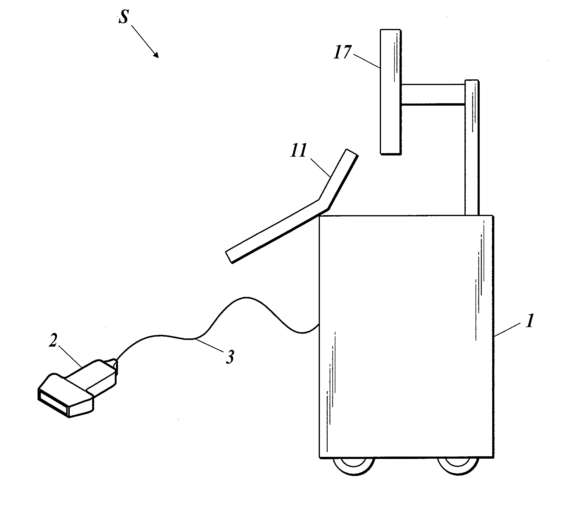
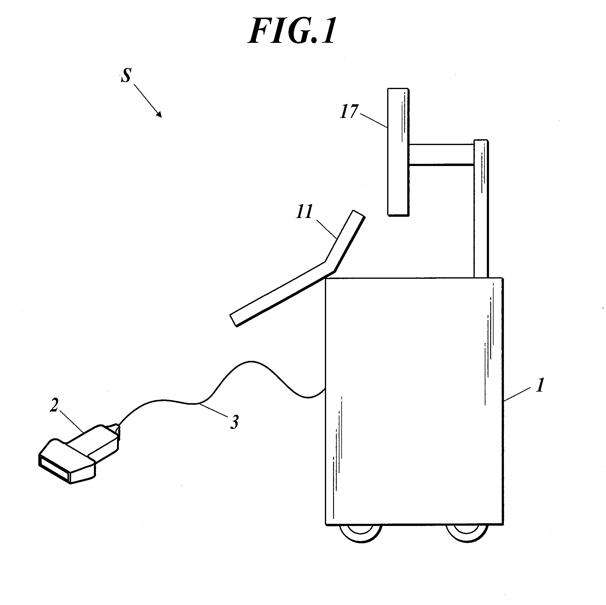
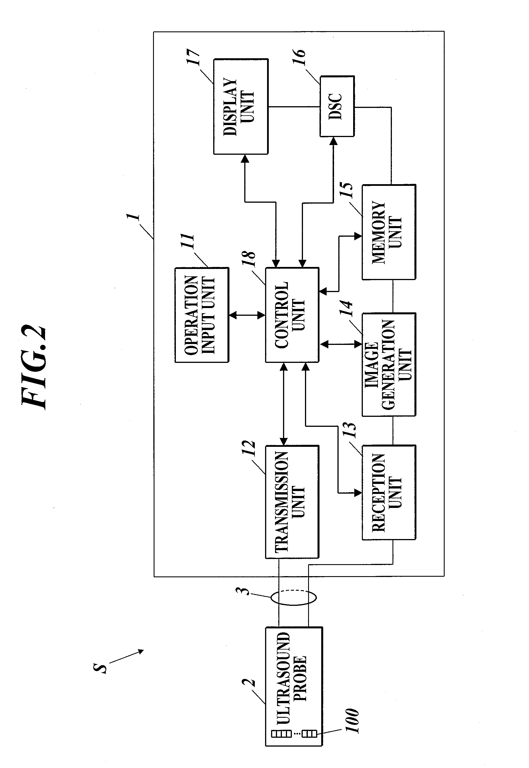
[0035]With reference to FIGS. 1 and 2, an ultrasound diagnostic imaging apparatus S according to the present embodiment includes a body 1 and an ultrasound probe 2.

[0036]The body 1 is connected to the ultrasound probe 2 with a cable 3. The body 1 supplies the ultrasound probe 2 with electric drive signals to cause the ultrasound probe 2 to emit ultrasound waves to a subject such as a living body (not shown), and creates an ultrasound image showing the interior of the subject on the basis of electric reception signals generated in the ultrasound probe 2 in response to reflected ultrasound waves (echoes) from the subject received by the ultrasound probe 2.

[0037]The ultrasound probe 2 emits ultrasound waves to the subject and receiv...

second embodiment

[0120]FIG. 7 is a schematic perspective view of an ultrasound probe 2A according to the second embodiment.

[0121]With reference to FIG. 7, the ultrasound probe 2A includes a stack 20A including a backing layer 21, a connecting conductor 22a, a heavy backing layer 25, and a piezoelectric layer 22, which are stacked in sequence from the bottom to the top; an acoustic matching layer 23 disposed on the piezoelectric layer 22; and an acoustic lens 24 disposed on the acoustic matching layer 23, for example.

[0122]The heavy backing layer 25 is a back reflecting layer provided between the piezoelectric layer 22 and the backing layer 21.

[0123]The heavy backing layer 25 is composed of a material having an acoustic impedance higher than that of the piezoelectric layer 22, and reflects ultrasound waves outputted in the direction opposite to a subject with respect to the piezoelectric layer 22. The heavy backing layer 25 can further increase the sensitivity to emitted and received ultrasound waves...

third embodiment

[0133]FIG. 9 is a schematic perspective view of an ultrasound probe 2B according to the third embodiment.

[0134]With reference to FIG. 9, the ultrasound probe 2B includes a stack 20B including a backing layer 21, a connecting conductor 22a, a heavy backing layer 25, and a piezoelectric layer 22, which are stacked in sequence from the bottom to the top; an acoustic matching layer 23 disposed on the piezoelectric layer 22; and an acoustic lens 24 disposed on the acoustic matching layer 23, for example.

[0135]In the ultrasound probe 2B according to the embodiment, primary slits 31 extend through the connecting conductor 22a.

[0136]Secondary slits 32 are shallower than the primary slits 31 and have bottoms located at a predetermined distance above the connecting conductor 22a.

[0137]In specific, the secondary slits 32 extend to a predetermined depth below the center in the thickness direction of the heavy backing layer 25.

[0138]The ratio of the depth of the primary slits 31 to that of the...


PUM


Abstract

An ultrasound probe includes a stack including a connecting conductor having conductive patterns and a piezoelectric plate disposed on the connecting conductor. The stack has first dividing slits at predetermined intervals. The first dividing slits divide the stack into transducers separate from one another and arrayed in the scanning direction. The conductive patterns are electrically connected to the transducers. Each of the transducers has a second dividing slit parallel to the first dividing slits. The second dividing slit divides each of the transducers into subelements. The first dividing slits extend through the connecting conductor. The second dividing slits are shallower than the first dividing slits and have bottoms apart from the connecting conductor.

Description

BACKGROUND OF THE INVENTION[0001]1. Field of the Invention[0002]The present invention relates to an ultrasound probe and an ultrasound diagnostic imaging apparatus.[0003]2. Description of Related Art[0004]A typical ultrasound diagnostic imaging apparatus scans the interior of a subject with ultrasound waves and creates an image showing the interior on the basis of reception signals generated in response to the reflected ultrasound waves from the subject.[0005]The ultrasound diagnostic imaging apparatus has an ultrasound probe emitting and receiving ultrasound waves to and from the subject.[0006]With reference to FIG. 11, the ultrasound probe includes a plurality of transducers 200 arrayed in the scanning direction, for example. The transducers 200 are formed by bonding a piezoelectric layer (plate) 71, which includes two electrodes having opposite polarities, to a backing layer 73, which reflects, attenuates, and absorbs ultrasound waves directed backward, via a connecting conductor...

Claims


Application Information

Patent Timeline
Patent Type & Authority Applications(United States)
IPC IPC(8): A61B8/00A61B8/14
CPCA61B8/14A61B8/4444A61B8/4494B06B1/0611B06B1/0622
Inventor UCHIBORI, MASAMI
Owner KONICA MINOLTA INC
Why Eureka
Try Eureka