Card edge LED strip connector and LED assembly

a technology of led strip and connector, which is applied in the direction of lighting and heating apparatus, coupling device connection, lighting support device, etc., can solve the problems of high maintenance costs of replacement bulbs, high labor and cost of bulbs, and high cost of replacement bulbs, so as to achieve easy manufacturing and assembly, and the effect of minimal spacing

Active Publication Date: 2012-10-30
KYOCERA AVX COMPONENTS CORP
View PDF18 Cites 100 Cited by
  • Summary
  • Abstract
  • Description
  • Claims
  • Application Information

AI Technical Summary

Benefits of technology

[0012]The contacts may take on any desired shape and configuration that ensures reliable electrical contact with the contact pads on the LED PCBs. In one embodiment, the electrical contacts include barbs on the contact arms disposed to slide against the connector pads. The contact arms may be biased into the receipt channels, with the barbs further serving to allow for deflection of the contact arms upon insertion of the end of the LED PCB into the receipt channel.
[0014]The electrical connector between the LED PCBs allows for minimal spacing between the boards, and thus uniform spacing between the LED bulbs of adjacent boards. The center beam of the electrical contacts essentially defines the separation distance between the ends of adjacent LED PCBs. In a particular embodiment, the center beam has a longitudinal length of between 1 mm and 5 mm such that in an assembled state, the adjacent ends of the LED PCBs are spaced apart a minimal distance equal to between about 1 mm and 5 mm.
[0015]The present invention also encompasses an LED light tube assembly that is configured for receipt in a lighting fixture. This light tube assembly includes a light tube having an end cap connector at each opposite longitudinal end thereof. In this manner, the LED light tube assembly may resemble a conventional fluorescent light tube. A plurality of LED PCBs are connected in an end-to-end configuration within the light tube, with each of the LED PCBs having at least one LED bulb and electrical connector pads configured at each opposite end of the boards. The electrical connector pads on the extreme opposite ends of the connected boards are in electrical mating contact with the end cap connectors. As described above, an electrical connector connects the connector pads of aligned ends of adjacent LED PCBs within the light tube such that one end of a first LED PCB is in electrical contact to an end of a second LED PCB. In this manner, any desired number of LED PCBs can be connected in an end-to-end manner within the light tube. Thus, various sizes and power ratings of the light tube can be easily manufactured and assembled using a standard, single size LED PCB, end cap connectors, and board connectors. Only the length of the light tube would vary to accommodate the desired number of LED PCBs.
[0016]The LED light tube assembly is particularly unique in that it can be readily configured for receipt in an existing fluorescent light fixture. The end cap connectors would include pin contacts configured for receipt in receptacles in the fluorescent light fixture. Thus, the LED light tube can be a replacement bulb for existing fluorescent light fixtures.

Problems solved by technology

With incandescent bulbs, the expense is not only the cost of replacement bulbs, but the labor and costs associated with frequent replacement of the bulbs.
This expense can be significant where there are a large number of installed bulbs.
For example, the maintenance costs to replace bulbs in large office buildings, public transportation vehicles and systems, and the like, can be quite high.
In large lighting systems, the cost savings are enormous.
Unfortunately, due in part to the relatively high cost of LED lights, the art turned to fluorescent light bulbs and systems as an alternative to incandescent lights.
Fluorescent lighting circuits are more complex than incandescent lighting and generally requires professional installation and expensive components.
Fluorescent lighting is generally less attractive than incandescent lighting and can flicker noticeably and produce an uneven light that may bother some users.
Mercury is an essential component in the manufacturing of fluorescent light tubes, and is considered hazardous by the U.S. Environmental Protection Agency due to its ability to bioaccumulate within the environment.
The disposal of fluorescent light tubes is problematic for many municipalities, and a movement is underway in may locations to phase out the use of fluorescent lighting.
However, the costs of replacing the existing fluorescent light tube fixtures and circuitry in existing structures, vehicles, systems, and so forth, is cost prohibitive.

Method used


Image

  • Card edge LED strip connector and LED assembly
  • Card edge LED strip connector and LED assembly
  • Card edge LED strip connector and LED assembly

Examples


Embodiment Construction

[0029]Reference will now be made in detail embodiments of the invention, examples of which are illustrated in the drawings. The various embodiments are presented herein for sake of explaining aspects of the invention, and should not be interpreted as a limitation of the invention. For example, features illustrated or described with respect to one embodiment can be used with another embodiment to yield still a further embodiment. It is intended that the present invention include these and other modifications and variations as come within the scope and spirit of the invention.

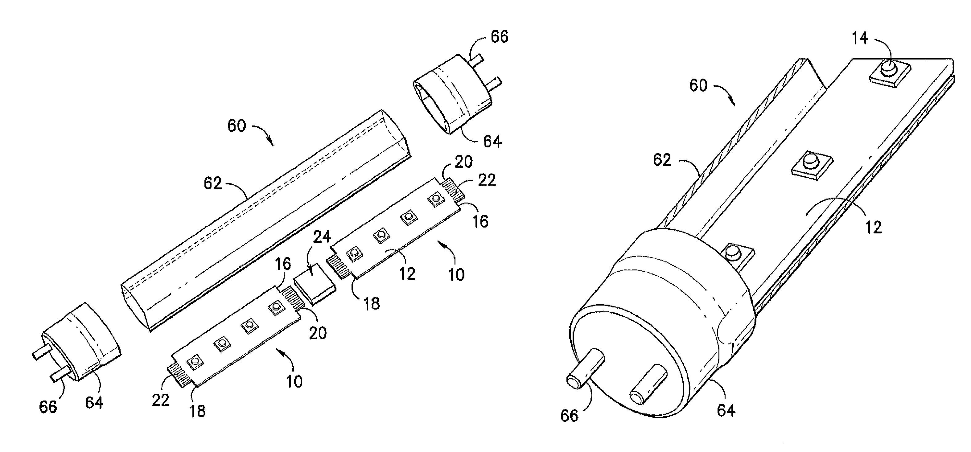
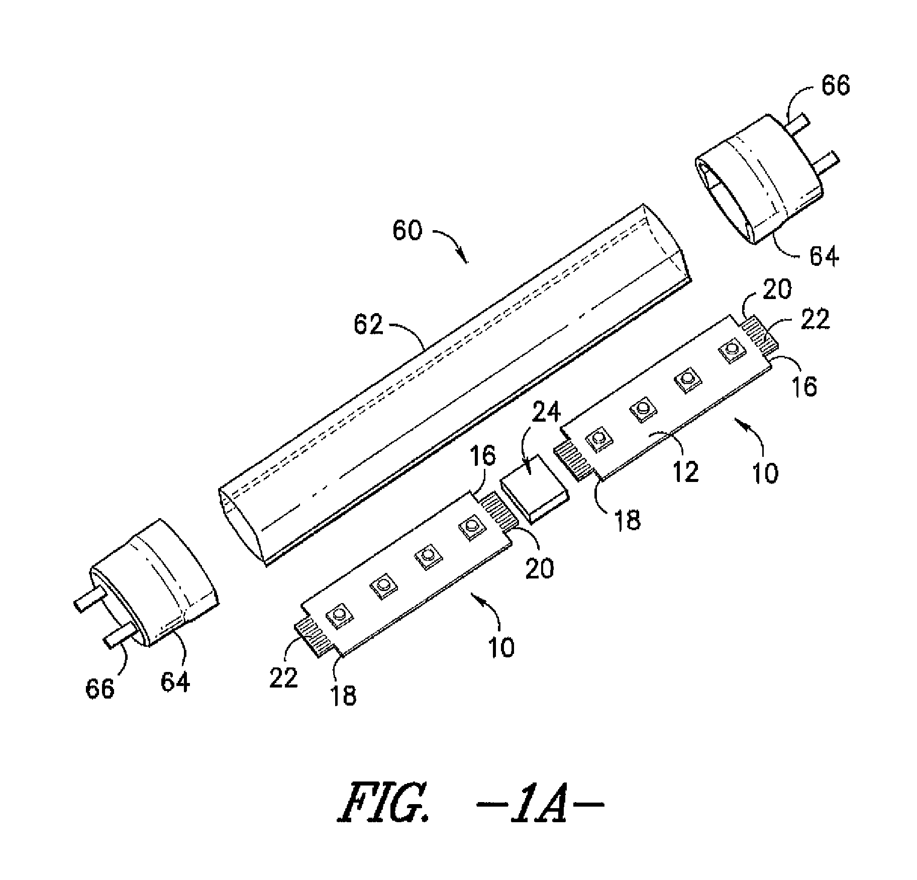
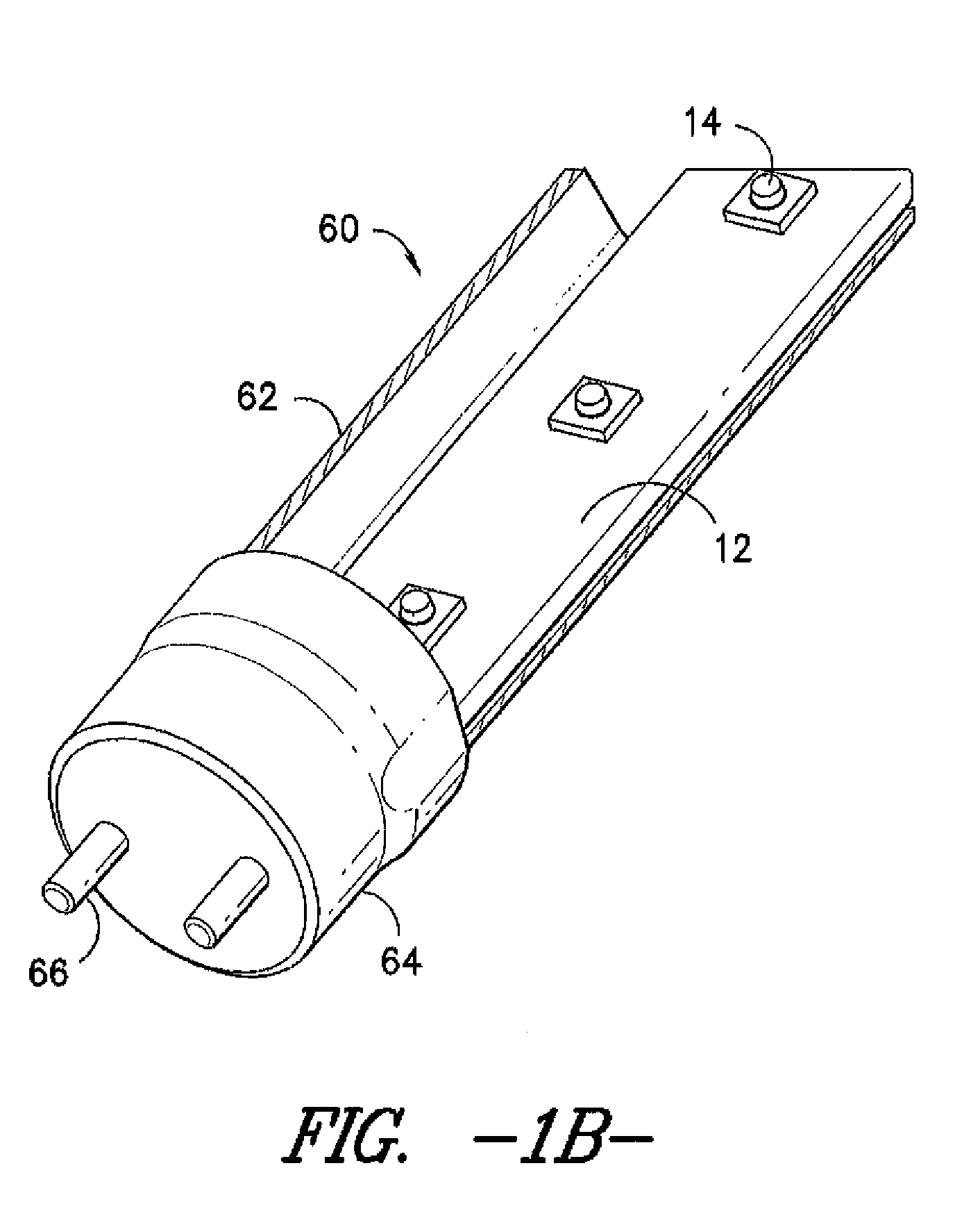
[0030]FIGS. 1A and 1B illustrate a particular embodiment incorporating aspects of the invention. An LED light assembly 10 is illustrated in FIG. 1A. This assembly 10 includes a plurality of individual LED printed circuit boards (PCB) 12. Each of these boards 12 includes at least one LED bulb 14. In the illustrated embodiment, each board 12 includes four bulbs 14. The boards 12 may be manufactured so as to have a ...


PUM


Abstract

An LED light assembly includes a plurality of LED printed circuit boards (PCB), with each LED PCB having at least one LED bulb and electrical connector pads configured at each opposite end of the boards. At least one electrical connector is configured to connect one end of a first LED PCB to an end of a second said LED PCB such that the first and second LED PCBs are electrically connected end-to-end. The connected LED PCBs may be configured in a light tube that includes connector end caps for mounting the light tube in a light fixture.

Description

BACKGROUND[0001]The use of LED (Light Emitting Diode) lights is becoming increasingly popular in a wide variety of lighting applications. Significant advances have been made in LED lighting technology, which have made the use of LED lights more affordable and desirable in various industrial, household, and other environments requiring expanded lighting systems.[0002]LED lights offer significant advantages over traditional incandescent lighting systems. With incandescent bulbs, the expense is not only the cost of replacement bulbs, but the labor and costs associated with frequent replacement of the bulbs. This expense can be significant where there are a large number of installed bulbs. For example, the maintenance costs to replace bulbs in large office buildings, public transportation vehicles and systems, and the like, can be quite high. These issues are substantially minimized with LED lighting systems.[0003]The operational life of conventional white LED lamps is about 100,000 hou...

Claims


Application Information

Patent Timeline
Patent Type & Authority Patents(United States)
IPC IPC(8): H01R12/00F21S4/00
CPCF21K9/17H05K1/142F21Y2101/02F21Y2103/00F21Y2103/003H05K2201/10106H05K2201/10189H05K1/117F21K9/27F21Y2103/10F21Y2115/10F21V23/06
Inventor BISHOP, PETER
Owner KYOCERA AVX COMPONENTS CORP
Why Eureka
Try Eureka