Lens unit and lens driving apparatus

a technology of lens holder and driving apparatus, which is applied in the direction of printers, instruments, cameras focusing arrangement, etc., can solve the problems of preventing the rotation of the screw rod or stopping the rotation of the screw rod, the lens held by the lens holder cannot be displaced smoothly, and it is difficult to maintain the posture of the lens holder with high accuracy. , to prevent the positioning accuracy of the lens from decreasing, the effect of smoothly displaced

Inactive Publication Date: 2012-10-30
SHARP KK
View PDF17 Cites 2 Cited by
  • Summary
  • Abstract
  • Description
  • Claims
  • Application Information

AI Technical Summary

Benefits of technology

[0018]An object of the invention is to provide a lens unit and a lens driving apparatus, which enable lenses to be displaced smoothly without increasing restriction with respect to distance between the lenses and moreover, prevent positioning accuracy of the lenses from decreasing.

Problems solved by technology

The increase in the friction resistance between the screw rod and the threaded portion impedes the rotation of the screw rod or stops the rotation of the screw rod.
Accordingly, the first conventional art as above has such a problem that the lens held by the lens holder cannot be displaced smoothly.
It is therefore difficult to maintain the posture of the lens holder with high accuracy in the case where the driving force-transmitting member contributes to the maintenance of the posture of the lens holder.
Accordingly, the second guide bush portion and the first rotation stop portion undesirably interfere with each other when the first lens and the second lens are brought close to each other, causing a problem that the first lens 4 and the second lens 9 cannot be sufficiently close to each other.
The fifth conventional art as above can solve the problem of the fourth conventional art, but has a problem that mounting errors for respective guide shafts accumulate to decrease positioning accuracy of the lenses since the first guide bush portion and the second guide portion slide on the different guide shafts and in addition, the first rotation stop portion and the second rotation stop portion slide on the different guide shafts.

Method used


Image

  • Lens unit and lens driving apparatus
  • Lens unit and lens driving apparatus
  • Lens unit and lens driving apparatus

Examples


Embodiment Construction

[0072]Now referring to the drawings, preferred embodiments of the invention are described below.

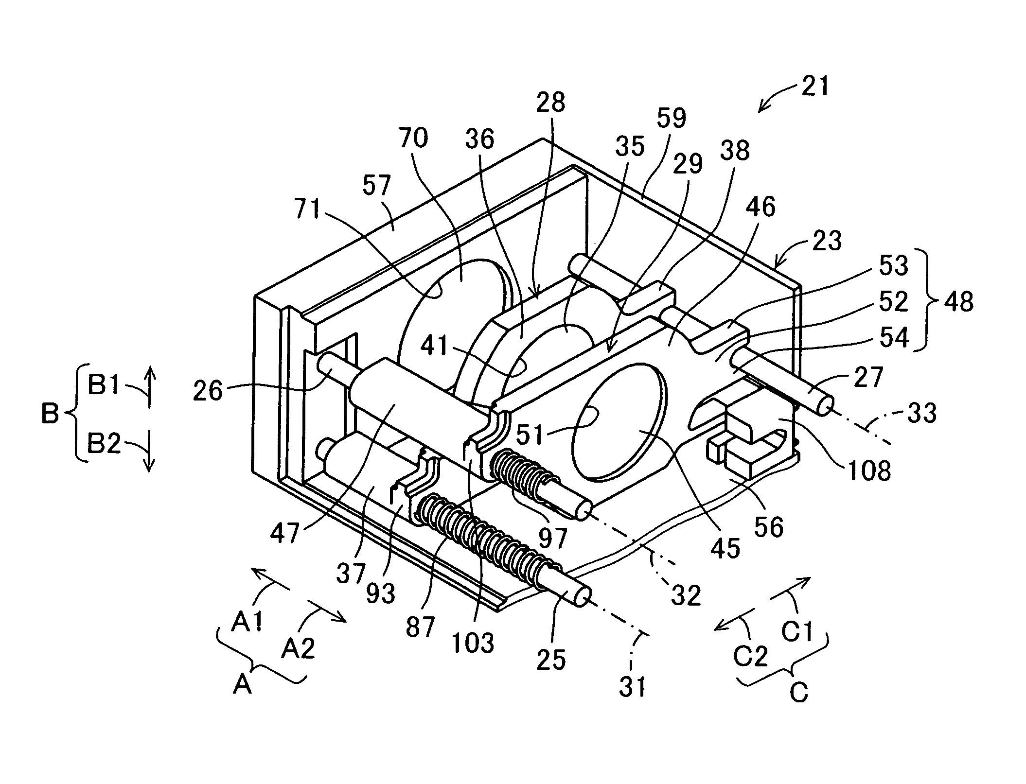
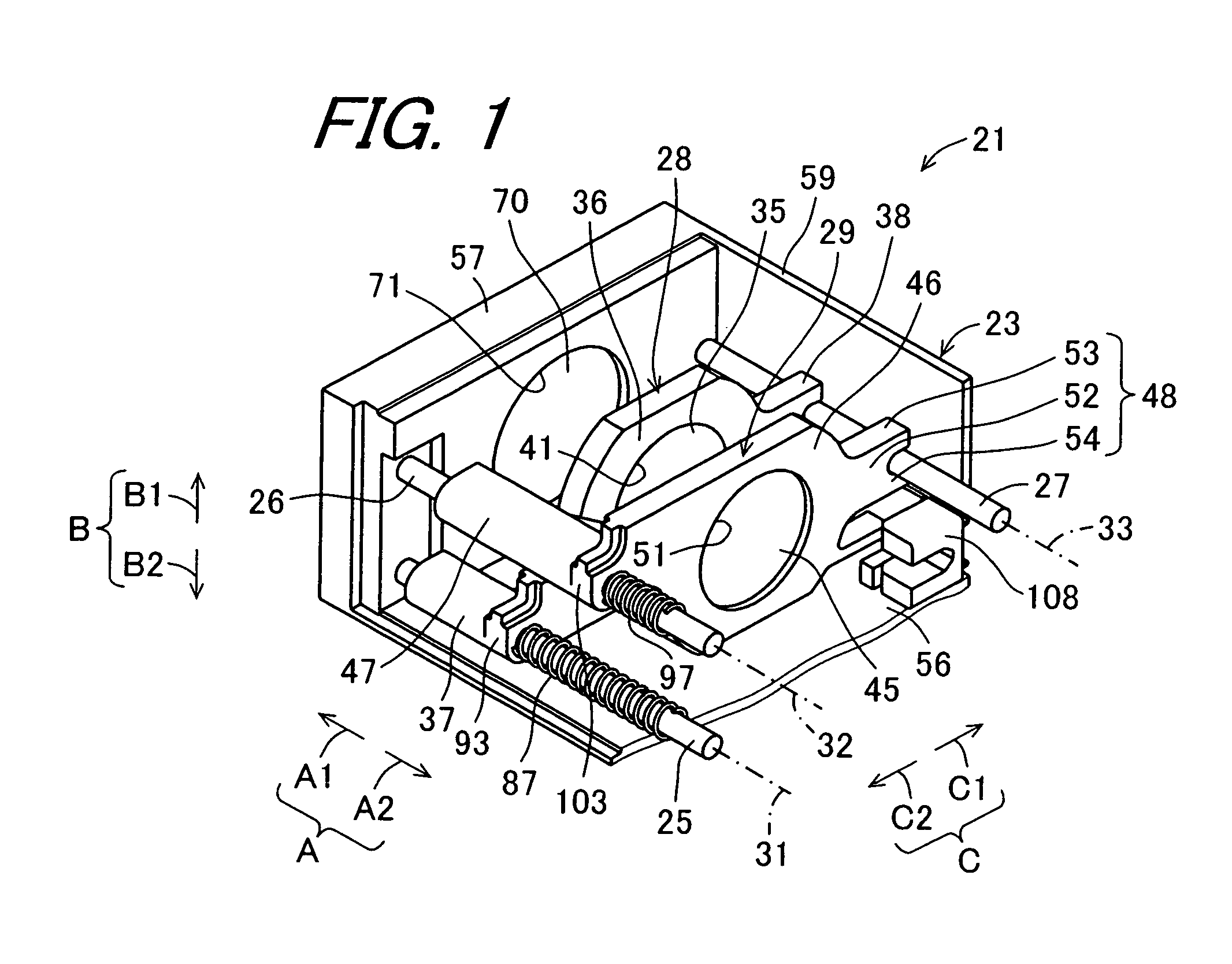
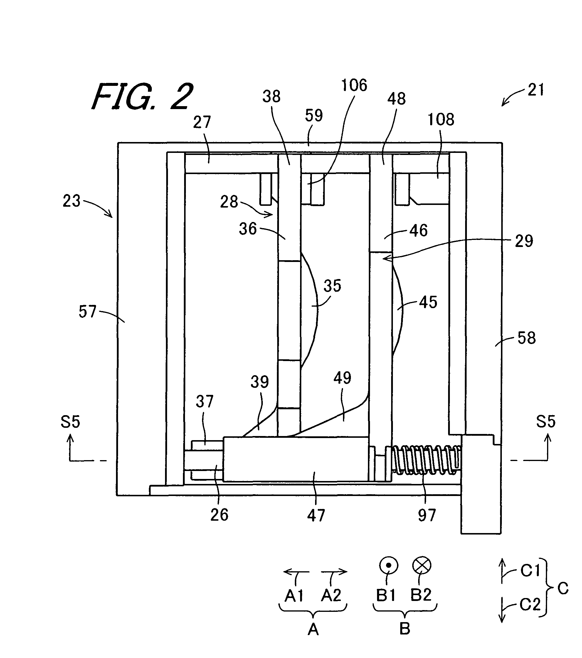
[0073]FIG. 1 is a perspective view showing a configuration of a lens unit 21 according to one embodiment of the invention. FIG. 2 is a plan view of the lens unit 21. In FIG. 1 and FIG. 2, a lid member 22 is omitted. In FIG. 1, a housing 23 is partially cut away.

[0074]The lens unit 21 of the present embodiment constitutes a part of an imaging apparatus 24 which is mounted on a mobile device such as a digital camera. The lens unit 21 includes a first guide member 25, a second guide member 26, a third guide member 27, a first lens holder 28, a second lens holder 29, the housing 23, and the lid member 22 (refer to FIG. 4).

[0075]The first guide member 25 has a first axis line 31. On the first guide member 25, a first guiding portion is formed which extends along the first axis line 31. The first guiding portion has sections perpendicular to the first axis line 31, of which sections have unifor...


PUM


Abstract

A lens unit and a lens driving apparatus are provided. First to third guide members have first to third axis lines, and the first to third axis lines are arranged in parallel with each other. A first lens holder has a first lens held by a first lens holding portion with a first main sliding portion guided by sliding on the first guide member, and a first sub sliding portion guided by sliding on the third guide member. A second lens holder has a second lens held coaxially with the first lens by a second lens holding portion with a second main sliding portion guided by sliding on the second guide member, and a second sub sliding portion guided by the third guide member.

Description

TECHNICAL FIELD[0001]The present invention relates to a lens unit for displacing a lens.[0002]Further, the present invention relates to a lens driving apparatus including the lens unit.BACKGROUND ART[0003]In an imaging apparatus, a plurality of lenses are coaxially provided, and when any of the respective lenses is displaced in optical directions thereof, an optical zoom is achieved. Later-described first to fifth conventional arts are well known as a technique for displacing a lens.[0004]The first conventional art is disclosed in Japanese Unexamined Patent Publication JP-A 2001-242366. In the first conventional art, a screw rod which rotates by means of an electromagnetic motor; and a guide shaft are arranged in parallel with each other. A lens holder has a holding portion which holds a lens, and a threaded portion into which the screw rod is inserted and threadably engaged. The lens holder is configured so that rotation about the screw rod is controlled by the guide shaft. When th...

Claims


Application Information

Patent Timeline
Patent Type & Authority Patents(United States)
IPC IPC(8): G02B7/02
CPCG02B7/102G03B3/02G03B3/10
Inventor KAWAMUKI, RYOHHEIFUJITA, HIDEAKINISHIKAWA, MASAYUKI
Owner SHARP KK
Why Eureka
Try Eureka