Motor control apparatus, image reading apparatus and image forming apparatus

a technology of motor control and image reading, which is applied in the direction of electronic commutation motor control, control system, dynamo-electric converter control, etc., can solve the problems of reducing positioning accuracy, unable to control the rotation amount of the rotor of the motor with high accuracy, and not being able to use vector control when starting the motor. , to achieve the effect of preventing the suffering of positioning accuracy

Active Publication Date: 2022-05-31
CANON KK
View PDF9 Cites 0 Cited by
  • Summary
  • Abstract
  • Description
  • Claims
  • Application Information

AI Technical Summary

Benefits of technology

[0005]The present invention has been made in view of the above problems. The present invention provides a technique for preventing positioning accuracy from suffering when using a motor as a driving source for positioning a moving object.
[0007]According to another aspect of the present invention, there is provided a motor control apparatus operable to control a motor, comprising: a speed determiner configured to determine a rotational speed of a rotor of the motor; and a controller having a first control mode for controlling a driving current flowing through the winding based on a current of a predetermined magnitude, and a second control mode for controlling a driving current flowing through the winding so that a deviation between a command speed representing a target speed of the rotor and a rotational speed determined by the speed determiner is reduced, wherein the controller executes the first control mode without executing the second control mode in a case of rotating the motor in a first direction, and executes the second control mode in a case of rotating the motor in a second direction which is a reverse direction to the first direction.
[0008]According to still another aspect of the present invention, there is provided an image reading apparatus comprising: a conveying roller configured to convey a document; a first reading device configured to read, at a reading position, an image of a document conveyed by the conveying roller; a discharging roller configured to discharge the document whose image was read by the first reading device; and a motor configured to drive a first load by rotating in a first direction and to drive a second load by rotating in a second direction that is a reverse direction to the first direction; and a motor control apparatus configured to control the motor, wherein the motor control apparatus comprising: a phase determiner for determining a rotational phase of a rotor of the motor; and a controller having a first control mode for controlling a driving current flowing through a winding of the motor based on a current of a predetermined magnitude, and a second control mode for controlling a driving current flowing through the winding so that a deviation between a command phase representing a target phase of the rotor and a rotational phase determined by the phase determiner is reduced, wherein the controller executes the first control mode without executing the second control mode in a case of rotating the motor in a first direction, and executes the second control mode in a case of rotating the motor in a second direction which is a reverse direction to the first direction.
[0009]According to yet another aspect of the present invention, there is provided an image reading apparatus, comprising: a conveying roller configured to convey a document; a first reading device configured to read, at a reading position, an image of a document conveyed by the conveying roller; a discharging roller configured to discharge the document whose image was read by the first reading device; and a motor configured to drive a first load by rotating in a first direction and to drive a second load by rotating in a second direction that is a reverse direction to the first direction; and a motor control apparatus configured to control the motor, wherein the motor control apparatus comprising: a speed determiner configured to determine a rotational speed of a rotor of the motor; and a controller having a first control mode for controlling a driving current flowing through the winding based on a current of a predetermined magnitude, and a second control mode for controlling a driving current flowing through the winding so that a deviation between a command speed representing a target speed of the rotor and a rotational speed determined by the speed determiner is reduced, wherein the controller executes the first control mode without executing the second control mode in a case of rotating the motor in a first direction, and executes the second control mode in a case of rotating the motor in a second direction which is a reverse direction to the first direction.
[0010]According to still another aspect of the present invention, there is provided an image forming apparatus, comprising: an image forming unit configured to form an image on a printing medium; and a conveying roller configured to convey the printing medium; a motor configured to drive a first load by rotating in a first direction and to drive a second load by rotating in a second direction that is a reverse direction to the first direction; and a motor control apparatus configured to control the motor, wherein the motor control apparatus comprising: a phase determiner for determining a rotational phase of a rotor of the motor; and a controller having a first control mode for controlling a driving current flowing through a winding of the motor based on a current of a predetermined magnitude, and a second control mode for controlling a driving current flowing through the winding so that a deviation between a command phase representing a target phase of the rotor and a rotational phase determined by the phase determiner is reduced, wherein the controller executes the first control mode without executing the second control mode in a case of rotating the motor in a first direction, and executes the second control mode in a case of rotating the motor in a second direction which is a reverse direction to the first direction.
[0011]According to yet another aspect of the present invention, there is provided an image forming apparatus, comprising: an image forming unit configured to form an image on a printing medium; and a conveying roller configured to convey the printing medium; a motor configured to drive a first load by rotating in a first direction and to drive a second load by rotating in a second direction that is a reverse direction to the first direction; and a motor control apparatus configured to control the motor, wherein the motor control apparatus comprising: a speed determiner configured to determine a rotational speed of a rotor of the motor; and a controller having a first control mode for controlling a driving current flowing through the winding based on a current of a predetermined magnitude, and a second control mode for controlling a driving current flowing through the winding so that a deviation between a command speed representing a target speed of the rotor and a rotational speed determined by the speed determiner is reduced, wherein the controller executes the first control mode without executing the second control mode in a case of rotating the motor in a first direction, and executes the second control mode in a case of rotating the motor in a second direction which is a reverse direction to the first direction.

Problems solved by technology

However, when a permanent magnet is used in a rotor, a counter-electromotive voltage is not generated and the rotational phase of the rotor cannot be detected in a state in which the rotor is not rotating, and therefore it is not possible to use vector control when starting the motor.
That is, it becomes impossible to control the rotation amount of the rotor of the motor with high accuracy.
This, leads to a decrease in positioning accuracy when controlling the position of a moving object by driving a cam mechanism by a motor for example.
Thus, when the motor is used as a driving source for positioning of the moving object, there is a problem in that the positioning accuracy of the moving object suffers due to the application of vector control.

Method used


Image

  • Motor control apparatus, image reading apparatus and image forming apparatus
  • Motor control apparatus, image reading apparatus and image forming apparatus
  • Motor control apparatus, image reading apparatus and image forming apparatus

Examples


first embodiment

[0022]In the following embodiment, a case where a motor control apparatus is provided in an image forming apparatus having a sheet conveyance apparatus for conveying a sheet of a printing medium, a document, or the like will be described. The image forming apparatus may be, for example, a multi-function device, a copying machine, a facsimile apparatus, a printer, or the like. Further, although an example in which the motor control apparatus of the present invention is applied to a two-phase stepping motor is described, the motor control apparatus of the present invention does not depend on the number of phases and the type of motor, and is also applicable to, for example, a three-phase brushless DC motor or the like.

[0023][Image Forming Apparatus]

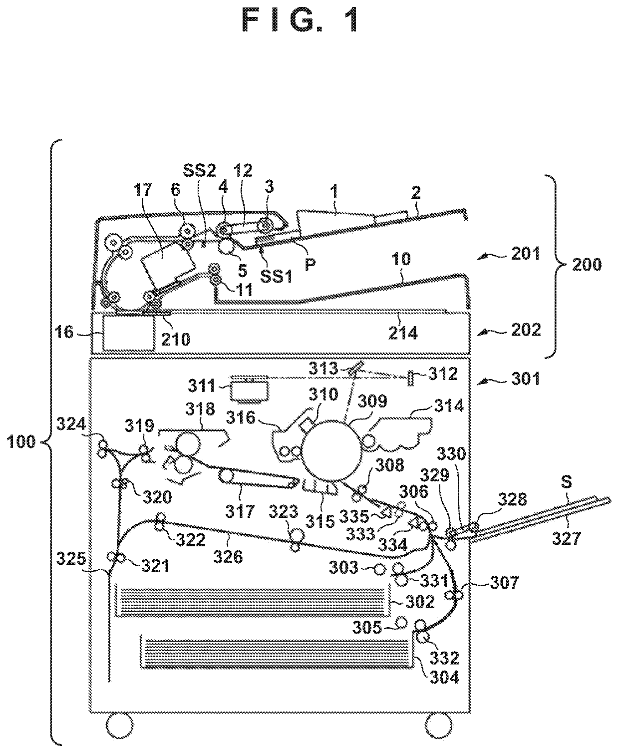
[0024]First, a configuration example of the image forming apparatus 100 in which the motor control apparatus is installed will be described with reference to FIG. 1. As shown in FIG. 1, the image forming apparatus 100 of the present embodim...

second embodiment

[0130]In the first embodiment, description was given of an example in which the movement mechanism of the glass unit 125 is configured to switch whether or not to transmit the driving force from the motor 122 to the cam 113 in accordance with the rotational direction of the rotor 401 of the motor 122. In the second embodiment, an example of control for driving the motor 122 by the motor control unit 123 for a case where the movement mechanism of the glass unit 125 is configured to switch whether to transmit the driving force from the motor 122 to the cam 113 using an electromagnetic clutch will be described. Note that below, mainly differences from the first embodiment will be described.

[0131]

[0132]FIG. 8 is a block diagram showing an example of a drive configuration of the cam 113 for moving the flow reading glass 101 according to the present embodiment. In the present embodiment, similarly to the first embodiment, it is assumed that a motor 122 is used as a driving source (first d...


PUM


Abstract

A motor control apparatus operable to control a motor includes a phase determiner for determining a rotational phase of a rotor of the motor, and a controller having a first control mode for controlling a driving current flowing through a winding of the motor based on a current of a predetermined magnitude, and a second control mode for controlling a driving current flowing through the winding so that a deviation between a command phase representing a target phase of the rotor and a rotational phase determined by the phase determiner is reduced. The controller executes the first control mode without executing the second control mode in a case of rotating the motor in a first direction, and executes the second control mode in a case of rotating the motor in a second direction which is a reverse direction to the first direction.

Description

BACKGROUND OF THE INVENTIONField of the Invention[0001]The present invention relates to drive control of a motor in a motor control apparatus, an image reading apparatus, and an image forming apparatus.Description of the Related Art[0002]In an image forming apparatus having a sheet conveyance apparatus that conveys a sheet such as a printing medium or a document, a stepping motor (hereinafter referred to as a “motor”) is widely used as a driving source of a conveying system for conveying the sheet. As a control method for driving control of a motor, a control method called vector control (or FOC (Field Oriented Control)) has been proposed.[0003]In the vector control as described above, it is necessary to detect the rotational phase of a rotor of the motor. By obtaining the rotational phase of the rotor based on a counter-electromotive voltage induced in the windings of each phase of the motor, it is possible to realize sensorless vector control which does not use a position sensor s...

Claims


Application Information

Patent Timeline
Patent Type & Authority Patents(United States)
IPC IPC(8): H02P6/185H02P6/22
CPCH02P6/185H02P6/22H02P8/22H02P21/24
Inventor OHASHI, YOHEI
Owner CANON KK
Why Eureka
Try Eureka