A high-precision explosion source location device for offshore platform tests
What is Al technical title?
Al technical title is built by PatSnap Al team. It summarizes the technical point description of the patent document.
An offshore platform, high-precision technology, applied in the direction of measuring devices, blasting, impact testing, etc., can solve the problems of large deflection of slender rods, non-reusable operation, broken positioning devices, etc., to reduce installation costs and simple structure , the effect of reducing the production cost
Active Publication Date: 2018-07-24
HARBIN ENG UNIV
View PDF4 Cites 0 Cited by
Summary
Abstract
Description
Claims
Application Information
AI Technical Summary
This helps you quickly interpret patents by identifying the three key elements:
Problems solved by technology
Method used
Benefits of technology
Problems solved by technology
In this case, due to the distance of the location of the explosion source, the slender rod has a large deflection problem, resulting in inaccurate location; at the same time, during the experiment, the location device is often broken due to the impact load of the explosion, so In each experiment process, it is necessary to repeatedly install the positioning rod, which not only increases the cost of the experiment, but also makes it very inconvenient to operate at sea
Therefore, the purpose of this device is to provide a high-precision mechanical positioning device for the offshore explosion shock test of the floating shock platform, and at the same time solve the problems of non-reusable and complicated operation in the traditional mechanical positioning device, and improve the operability of the offshore explosion test confidence in sex and test results
Method used
Image
Click on the blue label to locate the original text in one second.
Reading with bidirectional positioning of images and text.
Examples
Embodiment Construction
[0020] The present invention will be further described in detail below in conjunction with the accompanying drawings and specific embodiments.
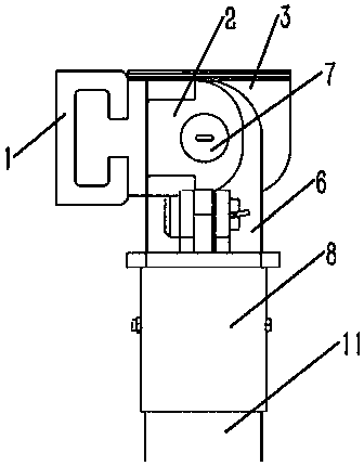
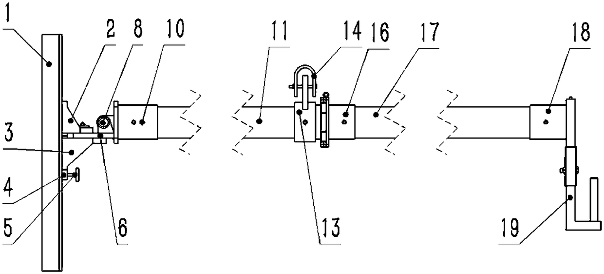
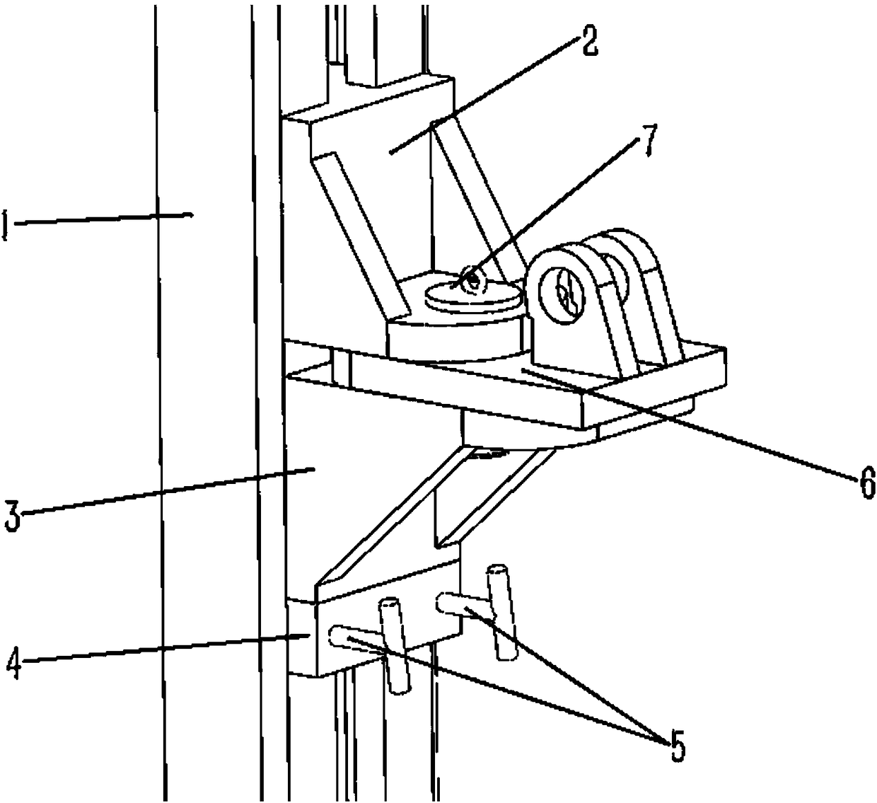
[0021] combine Figure 1 to Figure 8 , a device for mechanical positioning of a high-precision explosion source for an impact platform sea test of the present invention includes a fixed slide rail 1, an upper end slider 2, a lower end slider 3, a moving positioning block 4, a slider fastening bolt 5, a rotating Block 6, end pin 7, first-level connecting cylinder 8, movable pin 9, nail penetration 10, first-level extension rod 11, connecting piece 12, cushioning piece positioning piece 13, U-shaped cushioning rubber 14, hinge plate 15, two The first-stage connecting cylinder 16, the second-stage extension rod 17, the end mount 18, the buoy support 19, bolts, nuts, etc.; Sliding track: the upper end slider 2 and the lower end slider 3 are installed on the fixed slide rail, and can move freely in the track of the fixed slide rail 1, the...
PUM
Abstract
The invention provides an offshore platform test high-precision explosion source positioning device. The offshore platform test high-precision explosion source positioning device comprises a fixed sliding rail mounted on the outer wall of a floating impact platform, an upper end sliding block, a lower end sliding block, a moving positioning block, a rotating block, a first-stage connecting cylinder, a first-stage stretching rod, a connecting part, a turnover fold plate, a secondary connecting cylinder, a secondary stretching rod and an end mounting device; the upper end sliding block, the lower end sliding block and the moving positioning block are arranged in the fixed sliding rail from top to bottom, the rotating block is arranged between an upper end fixing block and a lower end fixing block through an end plug pin, the first-stage connecting cylinder is hinged to the rotating block, the first-stage stretching rod is connected with the end of the first-stage connecting cylinder, the connecting part is arranged at the end of the first-stage stretching rod, the turnover fold plate is hinged to the connecting part, the secondary connecting cylinder is connected with the end face of the fold plate, the secondary stretching rod is connected with the end of the secondary connecting cylinder, and the end mounting device is arranged at the end of the secondary connecting cylinder. The offshore platform test high-precision explosion source positioning device is simple in structure, convenient to mount and low in production cost, the device is characterized in that in the test on the floating impact platform, the accurate positioning of an explosion source is achieved, and meanwhile, the explosion source positioning device can be repeatedly dismounted and mounted.
Description
technical field [0001] The invention relates to a high-precision explosion source positioning device for offshore platform tests, belonging to the technical field of impact-resistant assessment tests for ship equipment. Background technique [0002] With the development of my country's naval technology and the increasing emphasis on marine affairs, my country has continuously increased its investment in research and development and production of naval equipment, and naval equipment often needs to conduct verification experiments of many performance parameters before it is officially delivered for use. Among the contents of the assessment, the assessment of its response to the underwater explosion attack is an important content. However, it is impossible to evaluate the explosion shock response of equipment on ships with actual ship tests. Some small equipment (light in weight) can be assessed by land impact machines. For large and medium-sized shipboard equipment, floating im...
Claims
Application Information
Patent Timeline
Application Date:The date an application was filed.
Publication Date:The date a patent or application was officially published.
First Publication Date:The earliest publication date of a patent with the same application number.
Issue Date:Publication date of the patent grant document.
PCT Entry Date:The Entry date of PCT National Phase.
Estimated Expiry Date:The statutory expiry date of a patent right according to the Patent Law, and it is the longest term of protection that the patent right can achieve without the termination of the patent right due to other reasons(Term extension factor has been taken into account ).
Invalid Date:Actual expiry date is based on effective date or publication date of legal transaction data of invalid patent.