Magnetic head for perpendicular magnetic recording having a main pole and a shield
a perpendicular magnetic and magnetic recording technology, applied in the direction of data recording, head winding construction, instruments, etc., can solve the problems of hindering the main pole from producing a write magnetic field of sufficient magnitude, conventionally difficult to allow the main pole, shortening the magnetic force produced, etc., to achieve the effect of reducing the length of the magnetic path
- Summary
- Abstract
- Description
- Claims
- Application Information
AI Technical Summary
Benefits of technology
Problems solved by technology
Method used
Image

Examples
first embodiment
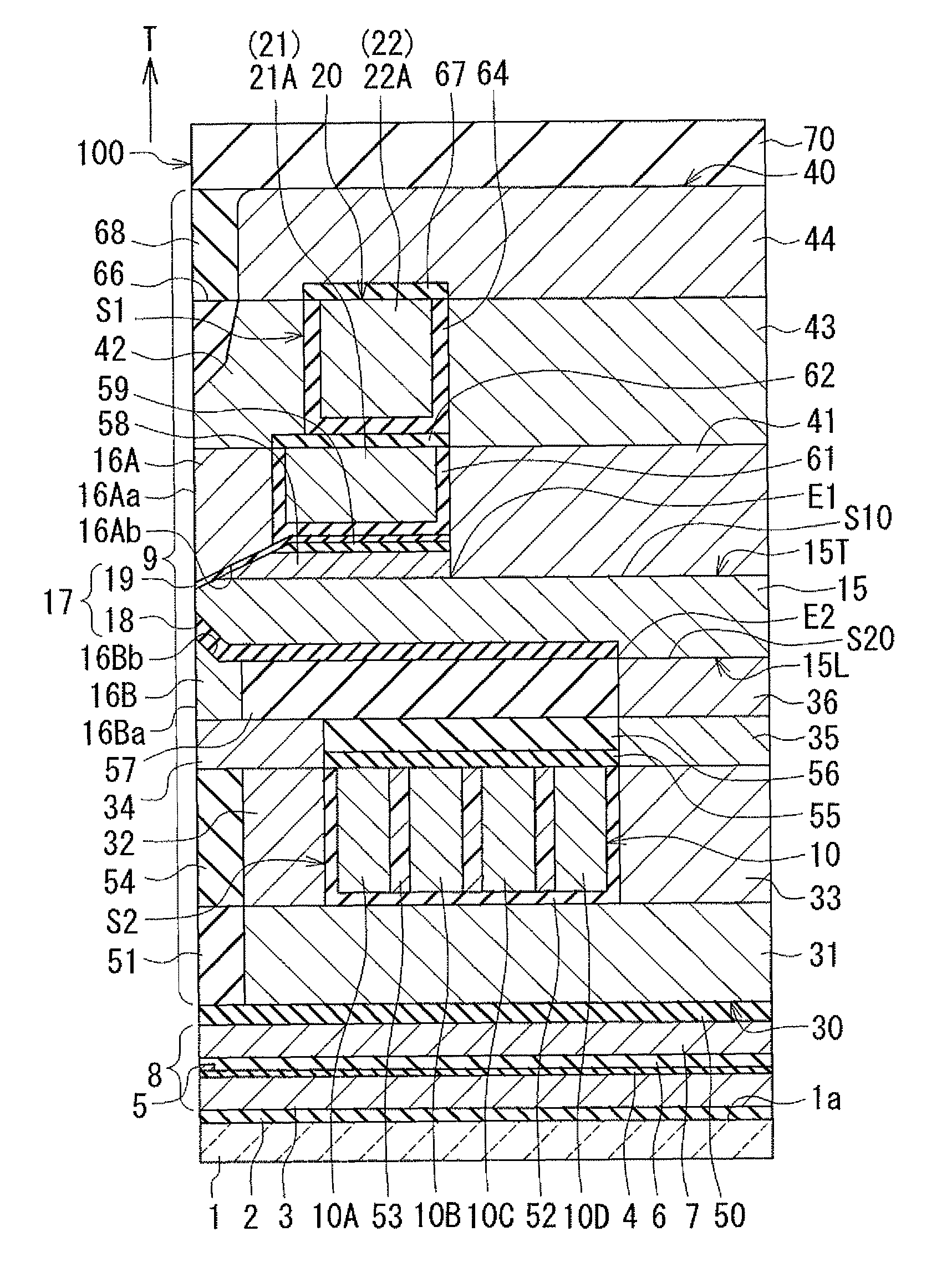
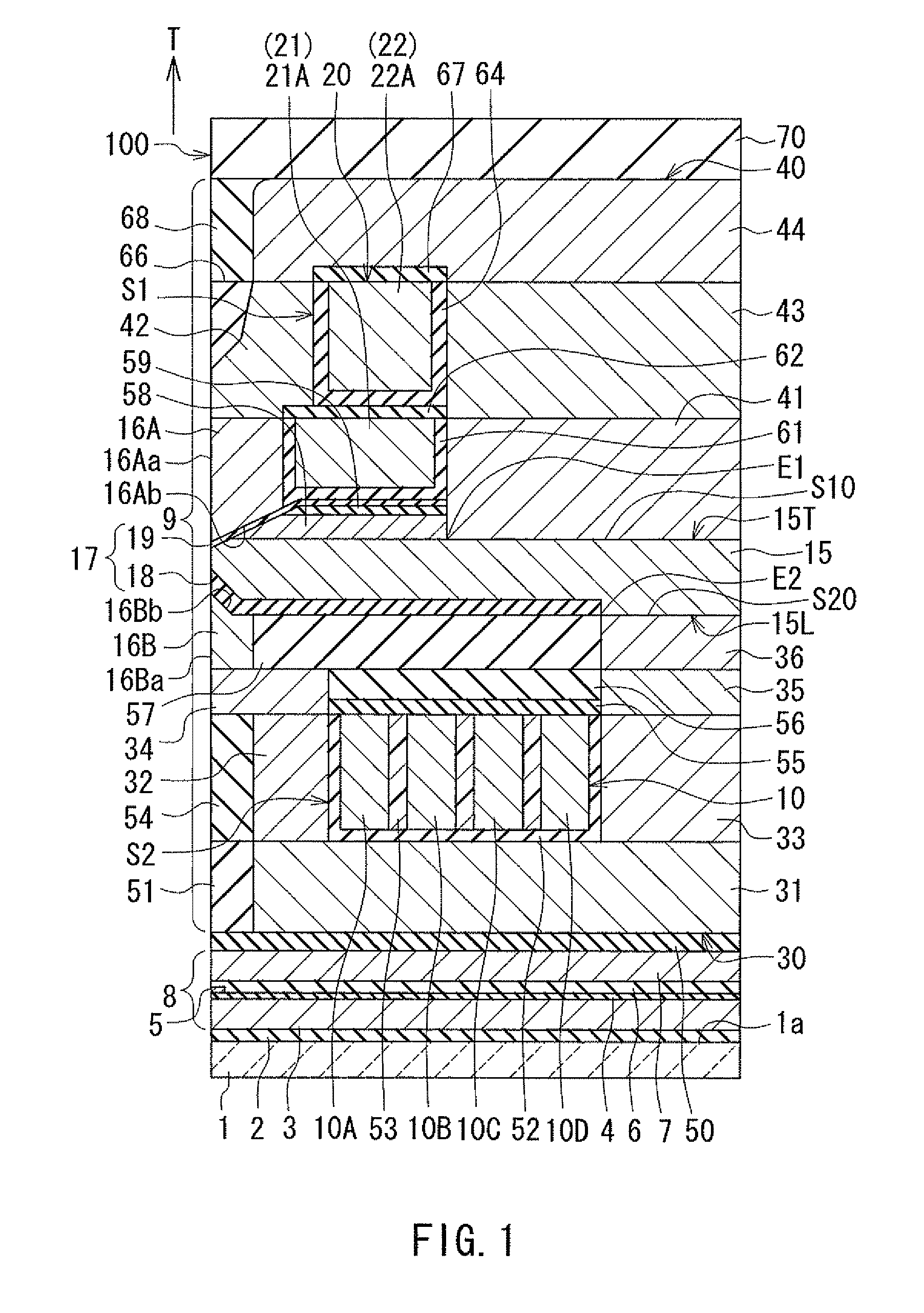
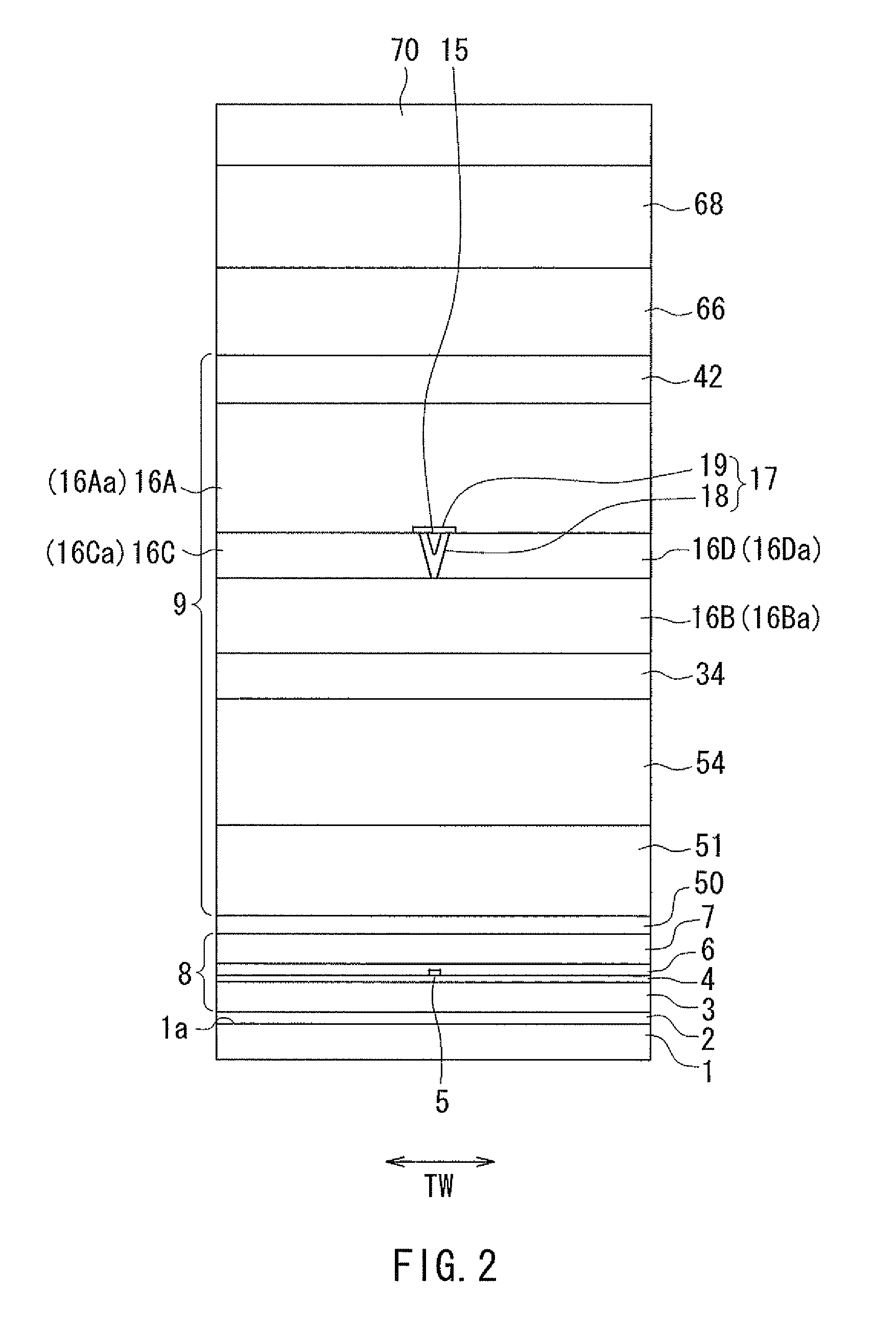
[0040]Embodiments of the present invention will now be described in detail with reference to the drawings. First, reference is made to FIG. 1 to FIG. 5 to describe the configuration of a magnetic head according to a first embodiment of the invention. FIG. 1 is a cross-sectional view of the magnetic head according to the present embodiment. Note that FIG. 1 show a cross section perpendicular to the medium facing surface and the top surface of the substrate. The arrow with the symbol T in FIG. 1 indicates the direction of travel of the recording medium. FIG. 2 is a front view showing the medium facing surface of the magnetic head according to the present embodiment. FIG. 3 is a plan view showing a second coil of the magnetic head according to the present embodiment. FIG. 4 is a plan view showing a first layer of a first coil of the magnetic head according to the present embodiment. FIG. 5 is a plan view showing a second layer of the first coil of the magnetic head according to the pre...
second embodiment
[0123]A magnetic head according to a second embodiment of the invention will now be described with reference to FIG. 8 and FIG. 9. FIG. 8 is a cross-sectional view of the magnetic head according to the present embodiment. Note that FIG. 8 shows a cross section perpendicular to the medium facing surface and the top surface of the substrate, or the main cross section, in particular. FIG. 9 is a plan view showing a second layer of a first coil of the magnetic head according to the present embodiment.
[0124]The configuration of the magnetic head according to the present embodiment is different from that of the magnetic head according to the first embodiment in the following respects. In the magnetic head according to the present embodiment, the first coil 20 includes a second layer 122 instead of the second layer 22 of the first embodiment. As shown in FIG. 9, the second layer 122 is wound approximately two turns around the magnetic layer 43 which constitutes a part of the first return p...
third embodiment
[0128]A magnetic head according to a third embodiment of the invention will now be described with reference to FIG. 10. FIG. 10 is a cross-sectional view of the magnetic head according to the present embodiment. Note that FIG. 10 shows a cross section perpendicular to the medium facing surface and the top surface of the substrate, or the main cross section, in particular.
[0129]The configuration of the magnetic head according to the present embodiment is different from that of the magnetic head according to the first embodiment in the following respects. The magnetic head according to the present embodiment is without the second shield 16B, the magnetic layers 34 to 36 and the insulating layers 55 and 56. The nonmagnetic layer 57 is disposed over the top surfaces of the second coil 10, the magnetic layer 32, the insulating film 52, and the insulating layers 53 and 54. Each of the magnetic layers 31 and 32 has an end face that is located in the medium facing surface 100 at a position ...
PUM
| Property | Measurement | Unit |
|---|---|---|
| thickness | aaaaa | aaaaa |
| thickness | aaaaa | aaaaa |
| height | aaaaa | aaaaa |
Abstract
Description
Claims
Application Information
 - R&D
- Intellectual Property
- Life Sciences
- Materials
- Tech Scout
- Unparalleled Data Quality
- Higher Quality Content
- 60% Fewer Hallucinations
Browse by: Latest US Patents, China's latest patents, Technical Efficacy Thesaurus, Application Domain, Technology Topic, Popular Technical Reports.
© 2025 PatSnap. All rights reserved.Legal|Privacy policy|Modern Slavery Act Transparency Statement|Sitemap|About US| Contact US: help@patsnap.com