Control apparatus

a control apparatus and control technology, applied in the direction of process and machine control, brake systems, instruments, etc., can solve the problems of uneven tire wear, affecting the traveling stability of the vehicle, and it is difficult to keep track of the actual traveling state of the vehicle, so as to improve the fuel consumption performance, increase or decrease the travel resistance of the vehicle, and reduce the effect of vehicle travel resistan

Active Publication Date: 2012-10-30
EQUOS RES
View PDF23 Cites 2 Cited by
  • Summary
  • Abstract
  • Description
  • Claims
  • Application Information

AI Technical Summary

Benefits of technology

[0021]According to the control apparatus of claim 1, the alignment control means controls the operating state of the alignment adjustment apparatus when the vehicle is traveling. After the alignment of the wheels is adjusted, the travel resistance of the vehicle is increased or decreased according to the alignment state of the wheels.
[0022]According to the present invention, the control apparatus includes the travel resistance detecting means for detecting the travel resistance of the vehicle, and the alignment control means controls the alignment adjustment apparatus based on the detection result of the travel resistance detecting means. That is, the alignment control means controls the alignment adjustment apparatus so that the travel resistance of the vehicle decreases. Thus, the alignment of the wheels when the vehicle is traveling can be adjusted to a proper state, whereby the fuel consumption performance can be improved.
[0023]According to the present invention, the alignment control means controls the alignment adjustment apparatus based on the detection result of the travel resistance detecting means. This eliminates the need to provide a sensor apparatus for detecting the alignment state of the wheels, whereby the overall product cost of the vehicle can be reduced accordingly.
[0024]Thus, the alignment control means does not control the alignment adjustment apparatus based on the alignment state detected by the sensor apparatus, but based on the travel resistance of the vehicle. Thus, the fuel consumption performance can be improved appropriately.
[0025]That is, in the case where the alignment state is detected by the sensor apparatus, detection accuracy of the sensor apparatus varies due to attachment accuracy of parts such as a suspension apparatus, deterioration of the tires due to aging and wear of the tires, and the like. Thus, a proper alignment state cannot be obtained by controlling the alignment adjustment apparatus based on the detection result of the sensor apparatus, and the travel resistance cannot be reduced sufficiently.
[0026]On the other hand, according to the present invention, the alignment adjustment apparatus is controlled based on the detection result of the travel resistance detecting means. Thus, a proper alignment state can be obtained even if vehicle parts such as a suspension apparatus is not attached with satisfactory accuracy, and tires have deteriorated due to aging or have worn, and the like. Thus, the travel resistance can be reliably reduced. As a result, the fuel consumption performance can be improved.

Problems solved by technology

Misalignment is caused by displacement of a suspension apparatus due to an impact that is applied when a vehicle is traveling, deterioration of tires due to aging, and the like, and affects traveling stability of the vehicle, uneven wear of the tires, and the like.
However, this technique has the following problem.
Thus, it is difficult to keep track of an actual traveling state of the vehicle, and adjustment cannot be made accurately.
That is, tires during traveling of the vehicle have characteristics such as deformation of the tire caused by a lateral force that is generated due to a slip angle, camber thrust that is generated due to the camber angle, and the relation between these forces and the rigidity of the tire, and non-uniformity due to a manufacturing error.

Method used


Image

  • Control apparatus
  • Control apparatus
  • Control apparatus

Examples


first embodiment

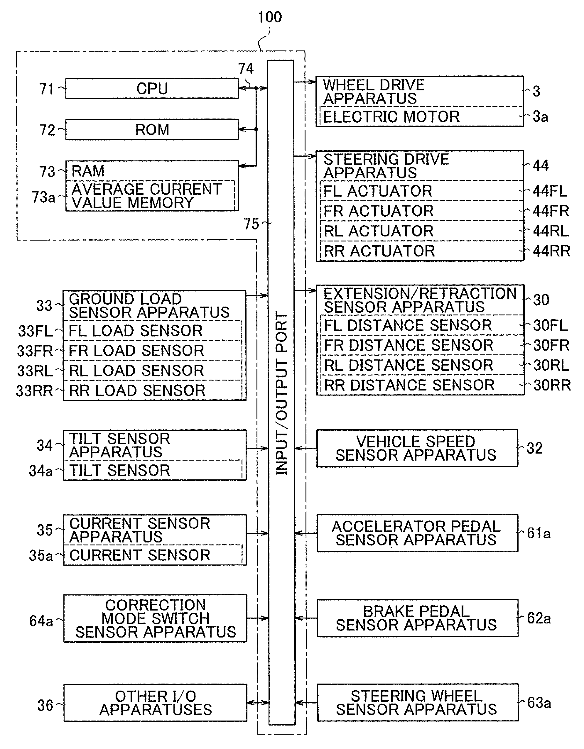
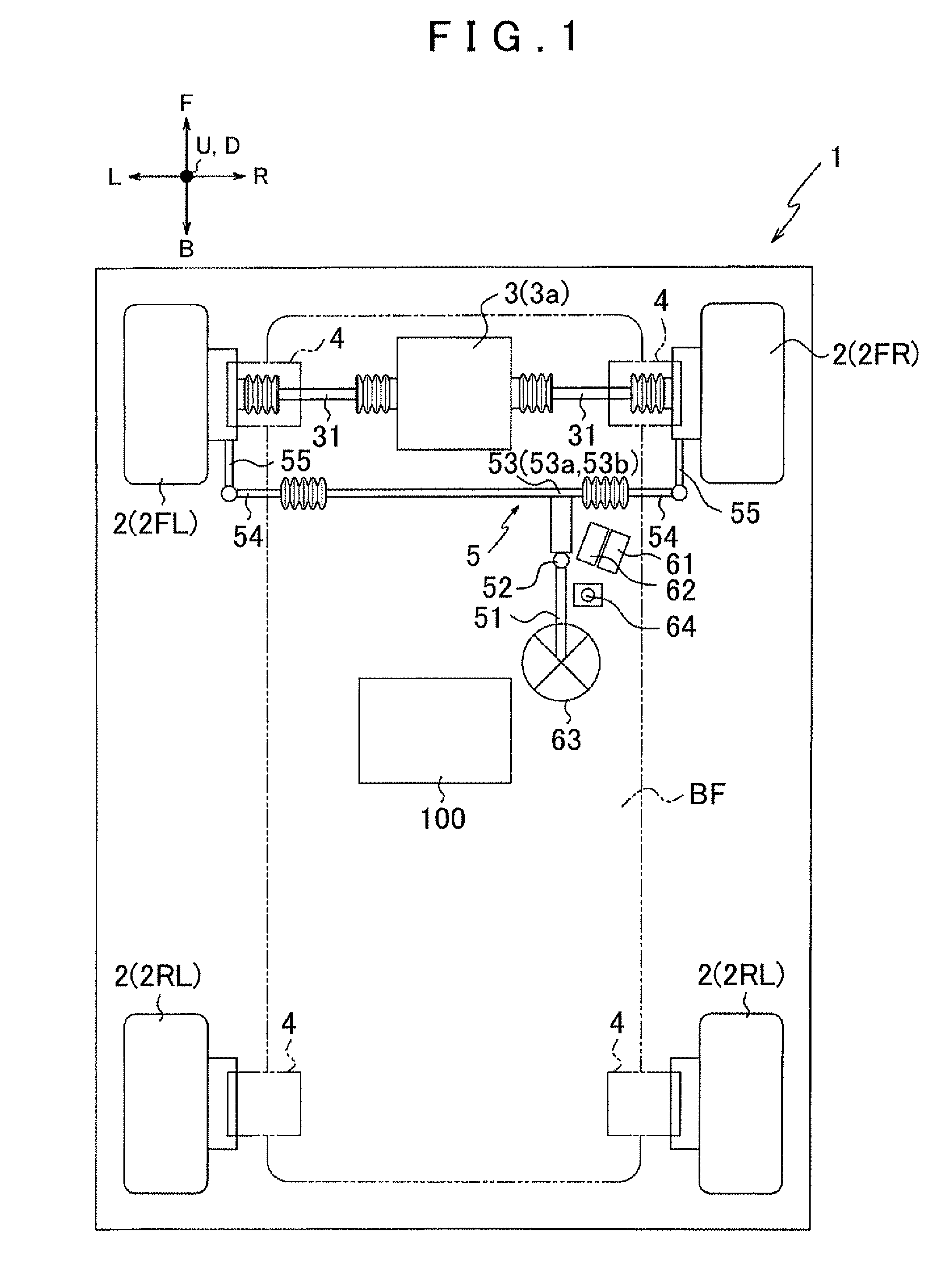
[0057]Preferred embodiments of the present invention will be described below with reference to the accompanying drawings. FIG. 1 is a diagram schematically showing a vehicle 1 to which a control apparatus 100 of the present invention is mounted. Note that arrows U-D, L-R, and F-B in FIG. 1 indicate the vertical, lateral, and longitudinal direction of the vehicle 1, respectively.

[0058]First, the general structure of the vehicle 1 will be described. As shown in FIG. 1, the vehicle 1 mainly includes: a vehicle body frame BF; a plurality of (four in the present embodiment) wheels 2 supported by the vehicle body frame BF; a wheel drive apparatus 3 for rotation driving a part of the wheels 2 (left and right front wheels 2FL, 2FR in the present embodiment); suspension apparatuses 4 for suspending the wheels 2 from the vehicle body frame BF in a floatable manner, respectively; and a steering device 5 as a steering apparatus for transmitting a steering operation of a steering wheel 63 to the...

second embodiment

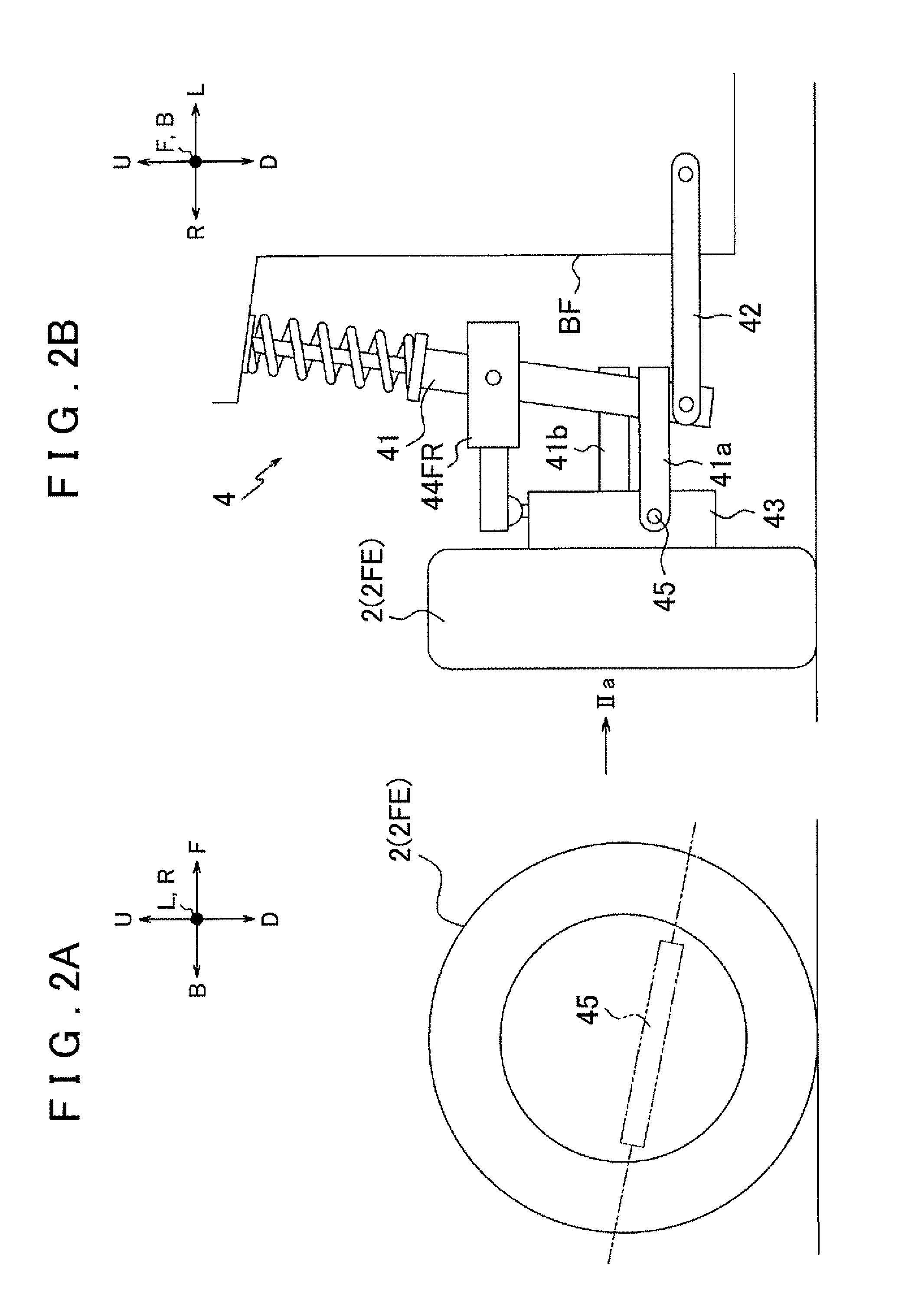
[0156]A second embodiment will be described below with reference to FIG. 8. FIG. 8A is a side view of a wheel 2, and FIG. 8B is a front view of a suspension apparatus 204. Note that FIG. 8A corresponds to a side view of the wheel 2 as viewed in the direction shown by arrow VIIIa in FIG. 8B. Note that arrows U-D, L-R, and F-B in FIG. 8 indicate the vertical, lateral, and longitudinal directions of a vehicle 1, respectively.

[0157]A total of four suspension apparatuses 204 are respectively provided for the wheels 2, and these suspension apparatuses 204 have the same structure. Thus, the suspension apparatus 204 corresponding to the right front wheel 2FR is shown in FIG. 8B as a representative example. It should be noted that a drive shaft 31, a tie rod 54, and the like are not shown in FIG. 8B in order to simplify the drawing and to facilitate understanding.

[0158]Although the first embodiment has been described with respect to the case where each suspension apparatus 4 is a strut suspe...


PUM


Abstract

A control device corrects the alignment of wheels of a vehicle during travel to improve fuel consumption performance. Operating conditions of a suspension device (alignment adjustment device) are controlled by alignment control while the vehicle is traveling, and when the alignment of the wheels is adjusted, travel resistance of the vehicle increases or decreases. The control device detects the travel resistance of the vehicle based on the value of an electric current supplied to a wheel drive device (electric motor), and the alignment of the wheels is adjusted so that the travel resistance of the vehicle decreases. As a result, the alignment of the wheels during travel is adjusted to a correct state to improve fuel consumption performance.

Description

TECHNICAL FIELD[0001]The present invention relates to a control apparatus for use in a vehicle that includes a wheel and an alignment adjustment apparatus for adjusting the alignment of the wheel. More particularly, the present invention relates to a control apparatus capable of achieving proper alignment of the wheels of a vehicle when the vehicle is traveling, thereby improving fuel consumption performance.BACKGROUND ART[0002]The “alignment” refers to the alignment of wheels, that is, the angle of the wheels with respect to the traveling direction of a vehicle or the road surface. The alignment is mainly represented by a camber angle and a toe angle. Misalignment is caused by displacement of a suspension apparatus due to an impact that is applied when a vehicle is traveling, deterioration of tires due to aging, and the like, and affects traveling stability of the vehicle, uneven wear of the tires, and the like. Thus, the alignment is measured and adjusted by various apparatuses.[0...

Claims


Application Information

Patent Timeline
Patent Type & Authority Patents(United States)
IPC IPC(8): B60W10/30B60W10/20
CPCB62D17/00B60G2200/4622B60G2500/40
Inventor MIZUNO, AKIRAANDO, MASAOHORIGUCHI, MUNEHISANAITO, TAKASHI
Owner EQUOS RES
Why Eureka
Try Eureka