Liquid supply apparatus and image forming apparatus

a technology of liquid supply apparatus and liquid supply head, which is applied in the direction of printing, other printing apparatus, etc., can solve the problems of density unevenness in recorded images, variation in ink ejection characteristics, and reduction in the ejection amount or decrease of the flying velocity of ink, so as to reduce the cost, stabilize the ejection stability of each liquid ejection head, and eliminate the effect of density unevenness caused by the difference in liquid temperatur

Active Publication Date: 2012-11-06
FUJIFILM CORP
View PDF11 Cites 39 Cited by
  • Summary
  • Abstract
  • Description
  • Claims
  • Application Information

AI Technical Summary

Benefits of technology

[0012]The present invention has been conceived with the foregoing in view and it is an object of the present invention to provide a liquid supply apparatus and an image forming apparatus that can adjust the temperature of liquid supplied to a liquid ejection head and stabilize the ejection of the liquid ejection head, without increasing the cost significantly.
[0014]According to this aspect of the invention, by controlling each of the flow rate control valves provided respectively between the liquid temperature adjusting device and the heat exchange units, the supplied amount of liquid medium that is supplied to each heat exchange unit can be individually changed and the heat exchange ratio of liquid (ink) and liquid medium in each heat exchange unit can be varied for each heat exchange unit. As a result, the temperature of liquid supplied to each liquid ejection head can be individually adjusted, ejection stability of each liquid ejection head can be stabilized, and inconveniences such as density unevenness caused by the difference in liquid temperature can be eliminated. Further, since the temperature of liquid supplied to each liquid ejection head can be adjusted for each type of liquid (for example, for each color of liquid) only by changing the supplied amount of liquid medium supplied to each heat exchange unit, no excess temperature adjustment capability is required for each type of liquid and cost can be reduced.
[0018]According to this aspect of the invention, the flow rate of liquid supplied to each heat exchange unit can be adjusted by controlling together the opening and closing of electromagnetic valves provided in each parallel flow path. Further, by using electromagnetic valves that are cheaper and easier to control than flow rate control valves, it is possible to reduce the cost of the liquid supply apparatus.
[0024]According to this aspect of the invention, by adjusting the flow rate of liquid medium supplied to the heat exchange units correspondingly to the temperature of liquid inside the liquid ejection heads, it is possible to set the liquid inside the liquid ejection heads to desired temperature.
[0029]In this aspect of the invention, the flow rate of liquid medium supplied to the heat exchange units is desirably adjusted according to the ejection ratios of the liquid ejection heads. There is a correlation between the ejection ratio of the liquid ejection head and the temperature of liquid inside thereof, and by adjusting the flow rate of liquid medium supplied to the heat exchange units on the basis of the ejection ratios of the liquid ejection heads, it is possible to set the liquid inside the liquid ejection heads to desired temperature.
[0033]According to the present invention, by controlling each of the flow rate control valves provided between the liquid temperature adjusting device and heat exchange units, the supplied amount of liquid medium that is supplied to each heat exchange unit can be individually changed and the heat exchange ratio of ink and liquid medium in each heat exchange unit can be varied for each heat exchange unit. As a result, the temperature of liquid supplied to each liquid ejection head can be individually adjusted, ejection stability of each liquid ejection head can be stabilized, and inconveniences such as density unevenness caused by the difference in liquid temperature can be eliminated. Further, since the temperature of liquid supplied to each liquid ejection head can be adjusted for each type of liquid (for example, for each color of liquid) by changing the supplied amount of liquid medium supplied to each heat exchange unit, no excess temperature adjustment capability is required for each type of liquid and cost can be reduced.

Problems solved by technology

Therefore, when the temperature of ink supplied to the recording head changes, the ink viscosity changes, thereby causing variations in ink ejection characteristics.
For example, when the ink temperature decreases, the ink viscosity increases, causing reduction in the ejection amount or decrease in the flying velocity of the ink and creating density unevenness in the recorded image.
However, since the inkjet recording apparatus described in Japanese Patent Application Publication No. 3-104655 is provided with a temperature adjusting device for each ink color, the cost of the apparatus is raised.
Further, since the total amount of droplets to be ejected onto the recording medium is determined, when a temperature adjusting device is provided for each color, the temperature adjustment capability corresponding to the maximum droplet ejection amount is necessary for each color and an excess capability as a whole is required, thereby raising the cost.
The problem is that these requirements cannot be met by the temperature adjustment performed by air cooling, such as used in the inkjet recording apparatus described in Japanese Patent Application Publication No. 3-104655.
Using a water cooling system to adjust the temperature of ink supplied to the recording head can be also considered, but this approach could result in undesirable significant cost increase because the ink temperature is adjusted separately for each recording head.

Method used


Image

  • Liquid supply apparatus and image forming apparatus
  • Liquid supply apparatus and image forming apparatus
  • Liquid supply apparatus and image forming apparatus

Examples


first embodiment

[0096]FIG. 6 is a schematic drawing illustrating a configuration example of ink supply system according to a first embodiment. As shown in FIG. 6, the ink supply system according to the first embodiment is constituted mainly by a head 50, a liquid storage unit 100, a pump 102, and a heat exchange unit 104 for each ink color.

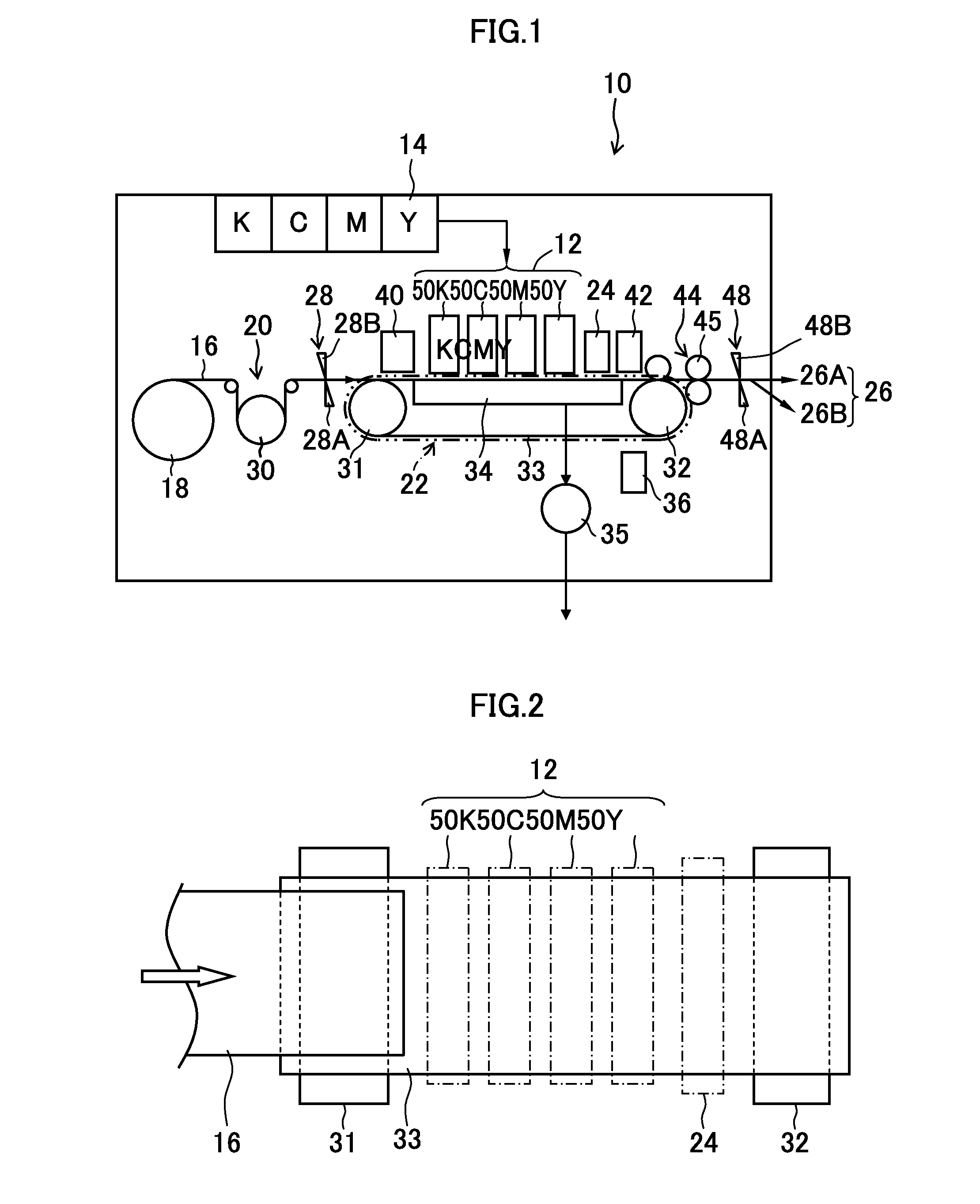
[0097]The ink storage unit 100 is a basic tank (ink supply source) accommodating ink for supply to each corresponding head 50 and corresponds to a tank disposed in the ink storage / loading unit 14 shown in FIG. 1.

[0098]The pump 102 is a pumping device installed between the liquid storage unit 100 and the head 50. By driving the pump 102, the ink is supplied from the liquid storage unit 100 to the head 50. In the configuration shown by way of the example in FIG. 6, the pump 102 is installed between the heat exchange unit 104 and the head 50, but this configuration is not limiting, and the pump 102 may be also installed between the liquid storage unit 100 and the he...

second embodiment

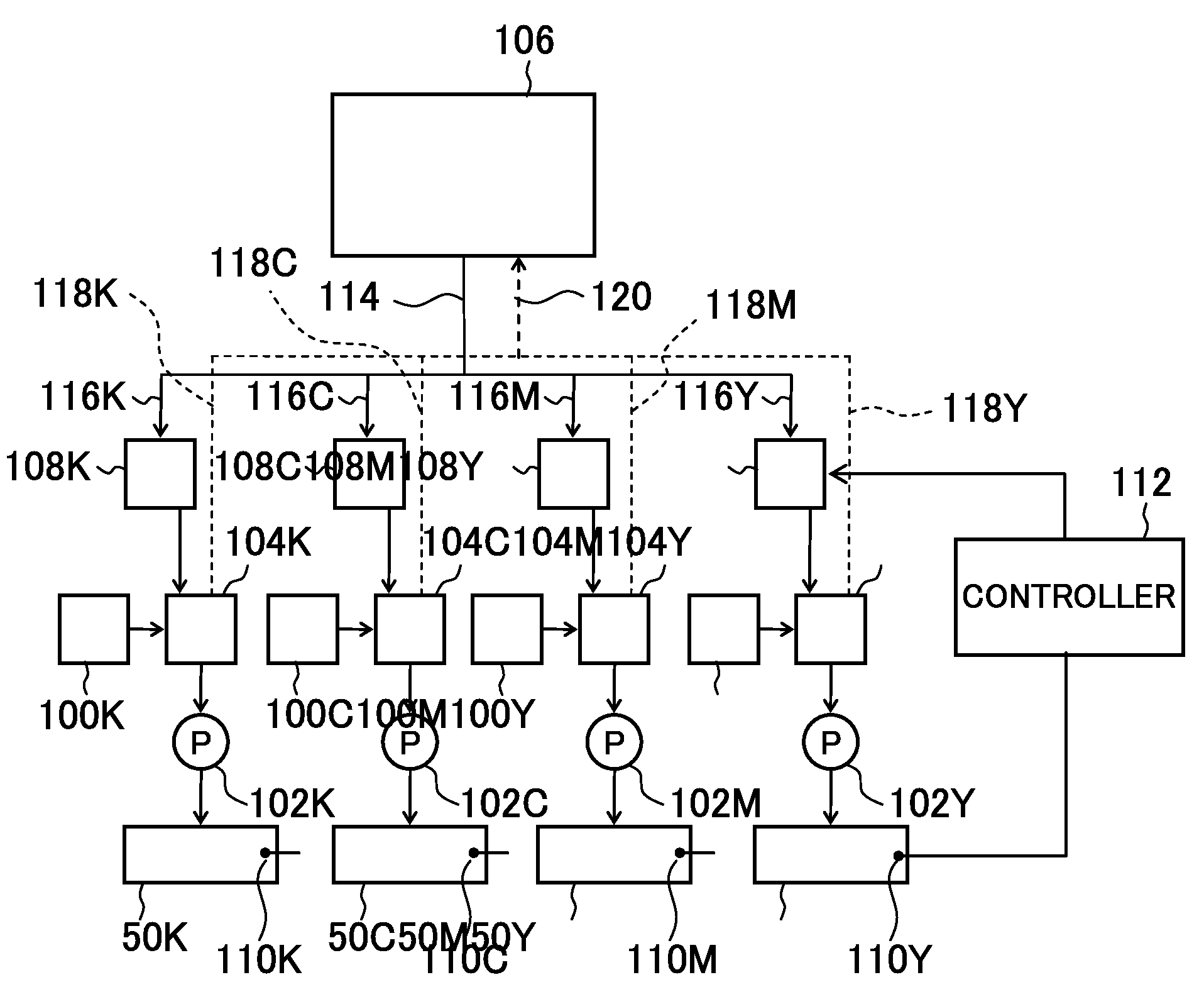
[0127]FIG. 10 is a schematic diagram illustrating a configuration example of an ink supply system according to a second embodiment. In FIG. 10, components common or analogous to those shown in FIG. 6 are assigned with like numeral symbols and explanation thereof is omitted. Further, components outside the configuration between the liquid temperature adjusting device 106 and the heat exchange units 104 (that is, the configuration between the liquid storage unit 100 and the heads 50) are similar to those of the configuration example shown in FIG. 6. Accordingly these components are not shown in FIG. 10.

[0128]As shown in FIG. 10, the ink supply system according to the second embodiment is similar to that of the first embodiment in that the liquid temperature adjusting device 106 and the heat exchange unit 104 are linked by a supply flow path 114 and each of a plurality of first branched flow paths 116 which branch off from the supply flow path 114 is provided with a flow rate adjusting...


PUM


Abstract

A liquid supply apparatus includes: a plurality of heat exchange devices which are respectively provided in a plurality of supply paths for supplying liquids to a plurality of liquid ejection heads respectively, are supplied with a liquid medium adjusted to a predetermined temperature from a liquid temperature adjusting device, and conduct heat exchange between the liquids flowing in the plurality of supply paths and the liquid medium supplied from the liquid temperature adjusting device; a plurality of flow rate adjusting devices which are respectively provided correspondingly to the plurality of heat exchange devices and adjust a flow rate of the liquid medium supplied to each of the plurality of heat exchange devices from the liquid temperature adjusting device; and a controller which controls each of the plurality of flow rate adjusting devices to individually change the flow rate of the liquid medium supplied from the liquid temperature adjusting device to the plurality of heat exchange devices.

Description

BACKGROUND OF THE INVENTION[0001]1. Field of the Invention[0002]The present invention relates to a liquid supply apparatus and an image forming apparatus, and more particularly to a technique for performing temperature control of a liquid supplied to a liquid ejection head.[0003]2. Description of the Related Art[0004]An inkjet recording apparatus is provided with a recording head (inkjet head) in which a plurality of nozzles are arranged in an ejection plane, and an image is formed on a recording medium by ejecting ink droplets from the nozzles, while the recording medium and the recording head are moved relative to each other. Examples of an ink ejection system of the recording head include a piezoelectric system in which the displacement of a piezoelectric element is used to pressurize the ink inside a pressure chamber and eject an ink droplet from the nozzle, and a thermal system in which thermal energy generated by a heat-generating element such as a heater is used to generate a...

Claims


Application Information

Patent Timeline
Patent Type & Authority Patents(United States)
IPC IPC(8): B41J29/377B41J2/175B41J29/28
CPCB41J2/175B41J2/17596
Inventor SHIBATA, HIROSHIKADOMATSU, TETSUZO
Owner FUJIFILM CORP
Why Eureka
Try Eureka