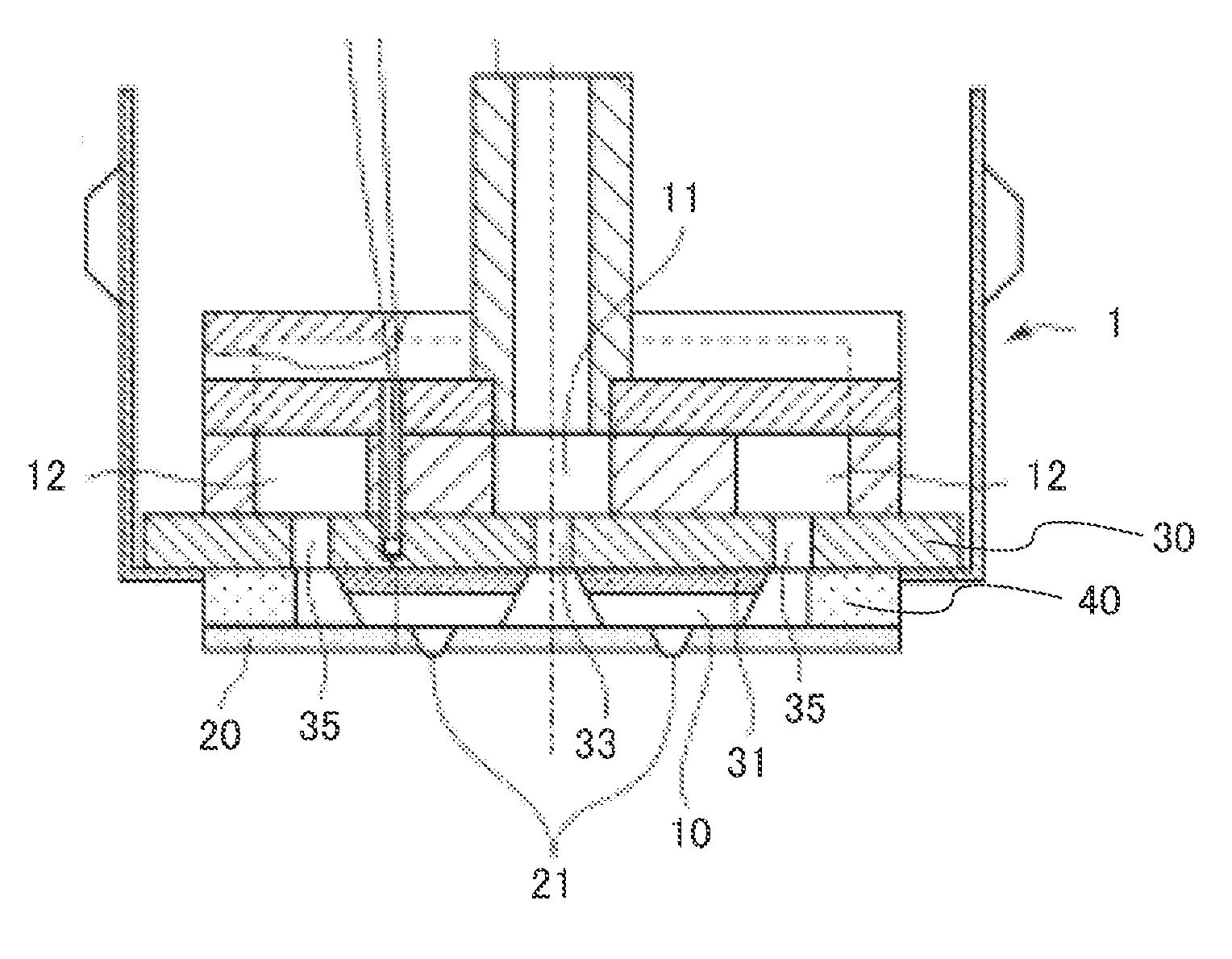
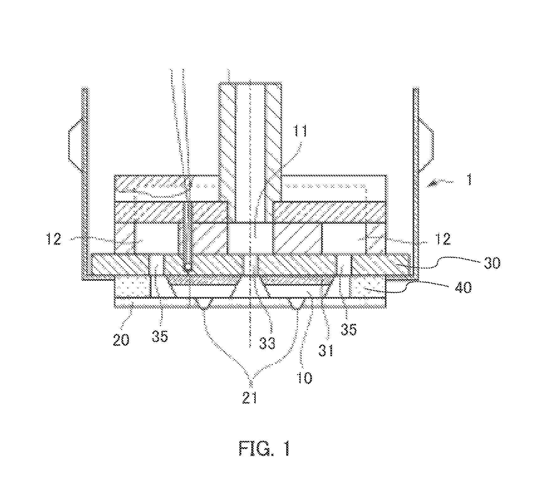
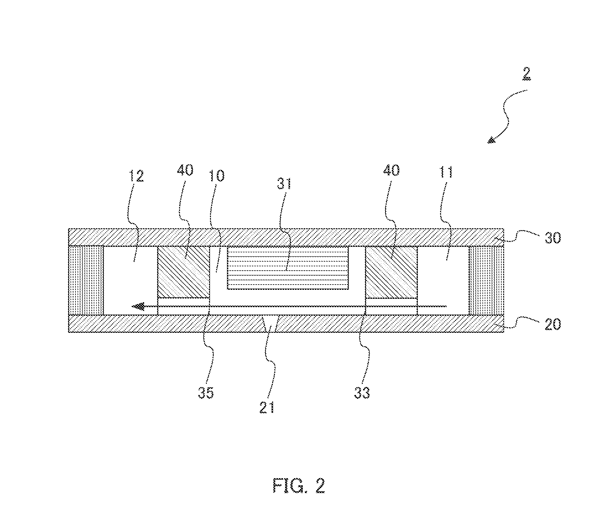
Ink-jet head and ink-jet apparatus
a technology of inkjet head and inkjet cartridge, which is applied in the direction of printing and inkjet cartridge, etc., can solve the problems of inability to enhance the ink discharge power, the inkjet head sometimes encounters problems, and the inkjet cartridge cannot accurately discharge ink droplets, etc., and achieves the effect of high ink discharge power and stably applying high viscosity ink
- Summary
- Abstract
- Description
- Claims
- Application Information
AI Technical Summary
Benefits of technology
Problems solved by technology
Method used
Image
Examples
embodiment 1
[0111]FIG. 3 is a perspective view of ink-jet head 100 of Embodiment 1 of the present invention. As illustrated in FIG. 3, ink-jet head 100 includes ink supply channel 101, ink discharge channel 102, and ink chambers 110.
[0112]Ink supply channel 101 includes ink feed port 103. Ink discharge channel 102 includes ink discharge port 104.
[0113]FIG. 4A is a sectional view, taken along line A, of ink-jet head 100 illustrated in FIG. 3. FIG. 4B is a sectional view, taken along line B, of ink-jet head 100 illustrated in FIG. 3. FIG. 4C is a sectional view, taken along line C, of ink-jet head 100 illustrated in FIG. 3.
[0114]As illustrated in FIGS. 4A to 4C, ink-jet head 100 includes nozzle 111 having discharge opening 112; multilayer piezoelectric element 113; ink inlet opening 121; ink inlet channel 123; ink outlet opening 125; and ink outlet channel 127.
[0115]Ink-jet head 100 further includes nozzle plate 130 having nozzle 111 and constituting a bottom surface of ink chamber 110; piezo-mou...
embodiment 2
[0136]Embodiment 1 describes an ink-jet head in which the ink inlet channel and ink outlet channel are linear. Embodiment 2 describes an ink-jet head in which the ink inlet channel and ink outlet channel have a bend.
[0137]FIG. 7 is a sectional view of ink-jet head 200 of Embodiment 2. Ink-jet head 200 is identical to ink-jet head 100 of Embodiment 1 illustrated in FIG. 4B except that the ink inlet channel and ink outlet channel have a bend, and the same elements are given to the same reference signs and their description is omitted.
[0138]As illustrated in FIG. 7, in ink-jet head 200 of this embodiment, ink inlet channel 223 and ink outlet channel 227 each has bend C. With this configuration, pressure drop in ink inlet channel 223 and ink outlet channel 227 increases. As a result, among forces generated by driving multilayer piezoelectric element 113, force F2 that travels in a direction perpendicular to ink discharge direction X becomes less likely to be released both from ink inlet...
embodiment 3
[0140]Embodiment 1 describes an ink-jet head in which the side surface (partition wall) of ink chambers is made perpendicular to the top surface (piezo-mounting plate) and to the bottom surface (nozzle plate). Embodiment 3 describes an ink-jet head in which a taper part is provided on the side surface of ink chambers.
[0141]FIG. 8 is a sectional view of ink-jet head 300 of Embodiment 3. Ink-jet head 300 is identical to ink-jet head 100 of Embodiment 1 illustrated in FIG. 4B except that a taper part is provided on the side surface of the ink chamber, and the same elements are given to the same reference signs and their description is omitted.
[0142]As illustrated in FIG. 8, in ink-jet head 300 of this embodiment, taper part 310 is formed on the side surface of ink chamber 110. More specifically, taper part 310 is formed on partition wall 150 opposite to partition wall 150 in which ink inlet opening 121 is formed. With this configuration, ink and air bubbles become less likely to stagna...
PUM
 Abstract
Description
Claims
Application Information
 - R&D
- Intellectual Property
- Life Sciences
- Materials
- Tech Scout
- Unparalleled Data Quality
- Higher Quality Content
- 60% Fewer Hallucinations
Browse by: Latest US Patents, China's latest patents, Technical Efficacy Thesaurus, Application Domain, Technology Topic, Popular Technical Reports.
© 2025 PatSnap. All rights reserved.Legal|Privacy policy|Modern Slavery Act Transparency Statement|Sitemap|About US| Contact US: help@patsnap.com


