Method and apparatus for pump protection without the use of traditional sensors

a technology of traditional sensors and pumps, applied in the field of pump protection, can solve the problems of device failure to include logic that would provide protection against undesirable operating conditions, and limited pumps, etc., and achieve the effect of accurately determining power vs flow and speed corrected power vs flow curv

Active Publication Date: 2012-11-06
ITT MFG ENTERPRISES LLC
View PDF23 Cites 58 Cited by
  • Summary
  • Abstract
  • Description
  • Claims
  • Application Information

AI Technical Summary

Problems solved by technology

However, this technique may be limited to pumps with constantly rising power curves from a closed valve condition.
Moreover, the following devices are known and all fail to include logic that differentiates undesirable operating conditions to control the pump appropriately for each condition without the use of traditional sensors and / or auxiliary controls.
However, this device fails to include logic that would provide for protection against undesirable operating conditions.
The device utilizes calibrated speed vs. torque curves which are application specific to obtain flow thereby reducing flexibility during field setup.
However, this device requires the use of instrumentation which adds cost and complexity to the drive system, a potential failure point, and unnecessary cost.
However, the Load Controls product is suitable only for constant speed applications and fails to provide control differentiation for various conditions; protective settings result in only “tripping” or shutting off of the motor.
However, this technique only protects against zero flow condition it does not include logic to detect a minimum flow condition (flow too low) or runout condition (flow too high) nor can it distinguish between a no demand condition or dry run condition.
However, this technique fails to include logic that would provide for protection against undesirable operating conditions.
This method requires application specific data to obtain flow thereby reducing flexibility during field setup.
However, the ABB drive does not provide logic for interpreting different operating conditions, nor does it allow for scaling of centrifugal loads, such as pumps or take into account mechanical losses in small pumps at reduced speed.
However, the use of additional process switches adds cost and complexity to the drive system, a potential failure point, and unnecessary cost.
Although widely used in the pump industry, affinity corrections to pump performance are not always accurate.
This method would require actual pump test data be used or risk introducing significant error.

Method used


Image

  • Method and apparatus for pump protection without the use of traditional sensors
  • Method and apparatus for pump protection without the use of traditional sensors
  • Method and apparatus for pump protection without the use of traditional sensors

Examples


Embodiment Construction

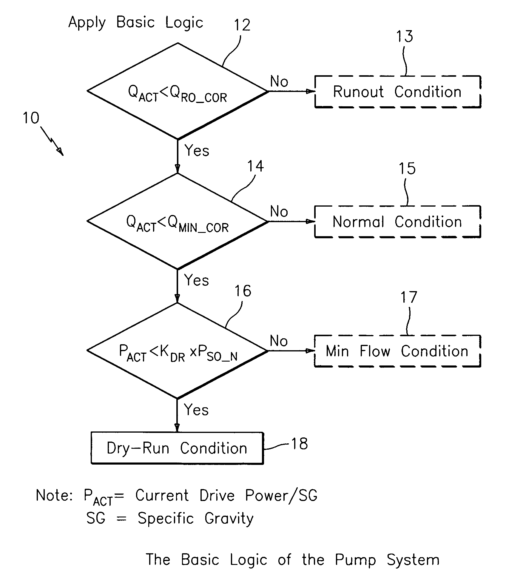
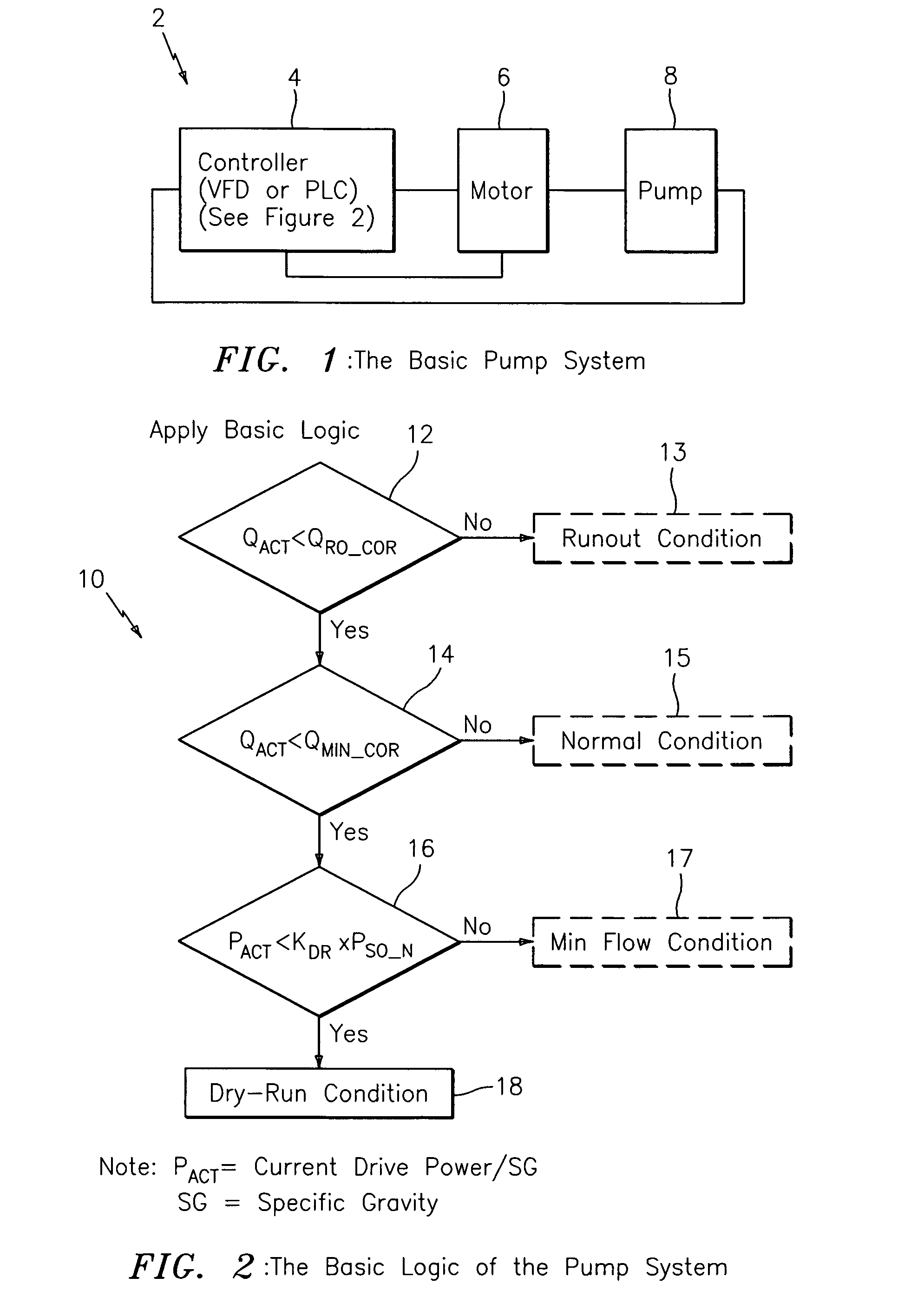
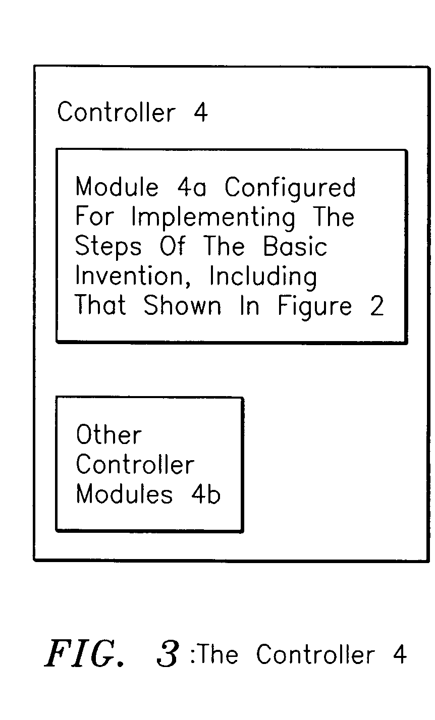
[0037]FIG. 1 shows the basic pump system generally indicated as 2 according to the present invention, having a controller 4, a motor 6 and a pump 8. In operation, the controller 4 according to the present invention determines the calculated flow value from a field calibrated speed vs closed valve power curve stored in the evaluation device and motor signals for speed and power (or torque) plus basic published pump performance data such as best efficiency power, closed valve power and best efficiency flow at the rated pump speed. The calculated flow input used for comparison to a threshold flow 15, value can also be taken from one of many techniques for calculating flow using pump affinity law data and flow calibration curves at various speeds stored in an evaluation device or module (such as module 4a in FIG. 3) and pump and motor signals such as speed and power (or torque), or speed and power / differential pressure. In cases where the installation includes a flowmeter, it can be use...


PUM


Abstract

The present invention provides protection for centrifugal pumps while differentiating between dangerous operating conditions (e.g. dry running, minimum flow and runout) and / or conditions where transient conditions (e.g. closed valve operation) may occur and the protection can be revoked once the condition clears. The methodology utilizes a calculated flow value which can be mathematically determined from a calibrated closed valve power vs speed curve and / or various pump and motor parameters such as speed, torque, power and / or differential pressure or from calibrated flow curves stored in the evaluation device. The calculated flow value is then compared to threshold values of flow associated with these adverse operating conditions.

Description

CROSS-REFERENCE TO RELATED APPLICATIONS[0001]This patent application claims benefit to provisional patent application Ser. No. 60 / 780,529, filed 8 Mar. 2006, entitled “Method for Pump Protection Without the Use of Traditional Sensors,” (911-2.22-1 / 05GI002), and is also related to provisional patent application Ser. No. 60 / 780,546, filed 8 Mar. 2006, entitled “Method For Determining Pump Flow Without Traditional Sensors,” (911-2.24-1 / 05GI003). Both of these provisional patent applications are incorporated herein by reference in their entirety.BACKGROUND OF THE INVENTION[0002]1. Field of the Invention[0003]The present invention relates to a pump system having a pump, including a centrifugal pump; and more particularly to a method and apparatus for pump protection without the use of traditional sensors.[0004]2. Brief Description of Related Art[0005]Other similar devices and their shortcomings are as follows:[0006]U.S. Pat. No. 7,080,508 discloses a method and apparatus for torque contr...

Claims


Application Information

Patent Timeline
Patent Type & Authority Patents(United States)
IPC IPC(8): F04B49/00
CPCF04D15/0088F04D15/0209F04D15/0218
Inventor STAVALE, ANTHONY E.GANZON, NICOLAS W.
Owner ITT MFG ENTERPRISES LLC
Why Eureka
Try Eureka