Connecting module with optical indication

a technology of connecting modules and optical indications, applied in the direction of connection, electrical apparatus, coupling device connection, etc., can solve the problems of user confusion in identifying the correct connecting module or the correct connecting device, the limited space available in the host, and the inability to easily find and identify the number or symbol

Active Publication Date: 2012-11-06
ASUSTEK COMPUTER INC
View PDF29 Cites 0 Cited by
  • Summary
  • Abstract
  • Description
  • Claims
  • Application Information

AI Technical Summary

Benefits of technology

[0007]The invention discloses a connecting module having a first connector with optical indication. With the function of the optical indication, the user may quickly identify the needed first connector.
[0009]Consequently, when connectors are connected to the first connectors, the electronic device may control the optical indicator to light functionally to guide the user to operate the correct first connector. Therefore, the user can find and operate the first connector correctly and quickly. Compared with the conventional technology, in the invention, even if the first connectors are disposed adjacently, the available space of the casing is limited, and the light in the environment is insufficient, the user still can find and identify the symbol easily with the optical indication of the electronic device, and he or she may identify the first connectors easily without mis-operating the first connector.

Problems solved by technology

However, if multiple devices with the same type are connected to connecting modules with the same type, and the connecting modules are arranged close to each other, the user may feel confused to identify the correct connecting module or the connecting device.
Since the server host also has many other electronic components, cables and so on, the available space in the host is rather limited, and the user cannot find and identify the numbers or symbols easily.
If the printed numbers or symbols are small, he or she may wrongly identify them, which easily happens in an environment with insufficient light.

Method used


Image

  • Connecting module with optical indication
  • Connecting module with optical indication
  • Connecting module with optical indication

Examples


first embodiment

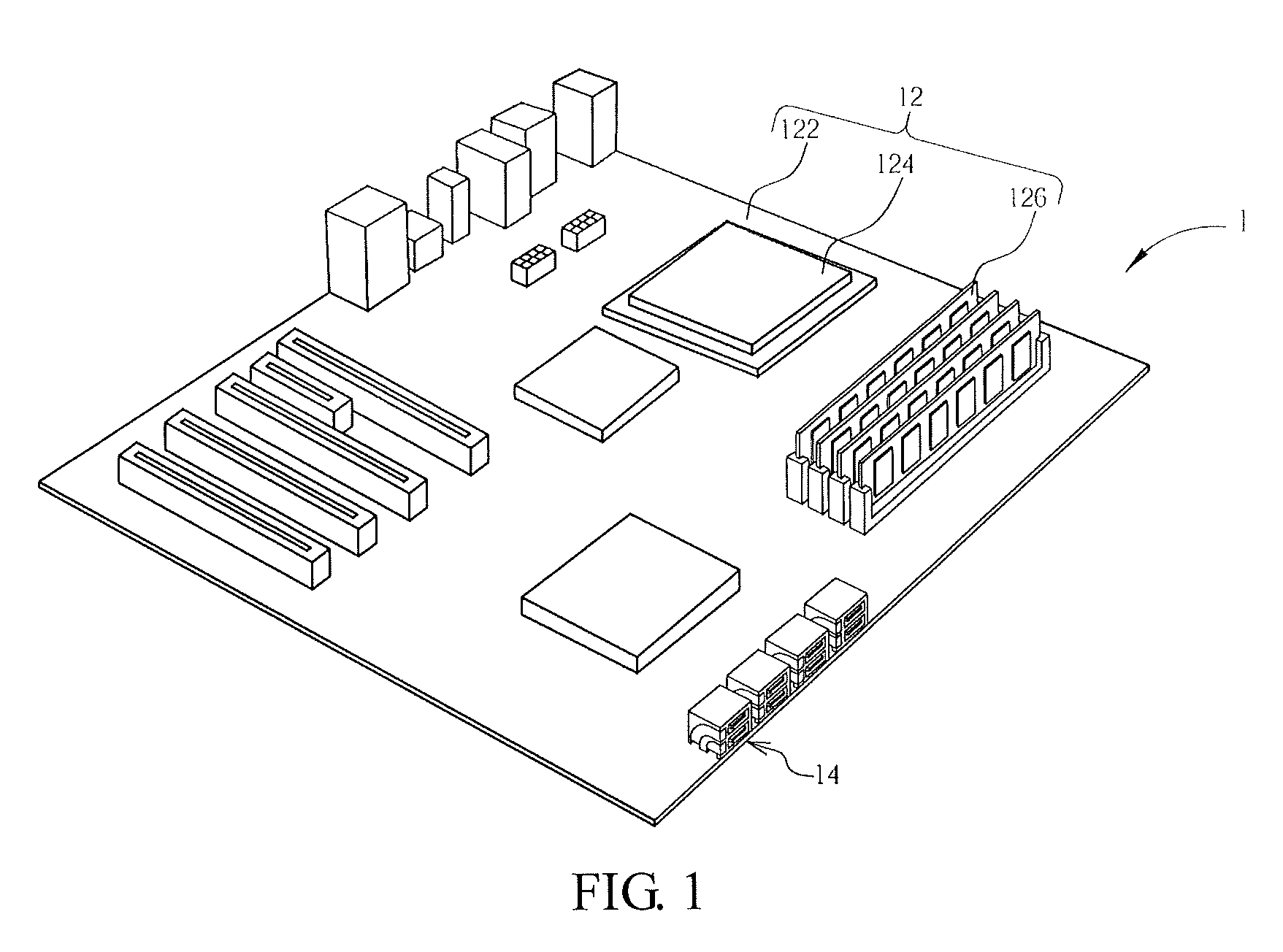
[0022]FIG. 1 is a schematic diagram showing an electronic device 1 in the invention. The electronic device 1 includes a processing module 12 and four connecting modules 14 electrically connected to the processing module 12. The processing module 12 includes a motherboard 122 and the elements on the motherboard such as a processor 124 and a memory 126. The connecting modules 14 are disposed on a motherboard 122 directly. In the embodiment, the connecting modules 14 are integrated connectors at the edge of the motherboard, and the invention is not limited thereto. The connecting modules 14 are disposed adjacently, and each connecting module 14 includes two first connectors piled with each other. Therefore, the electronic device 1 includes eight adjacent first connectors,

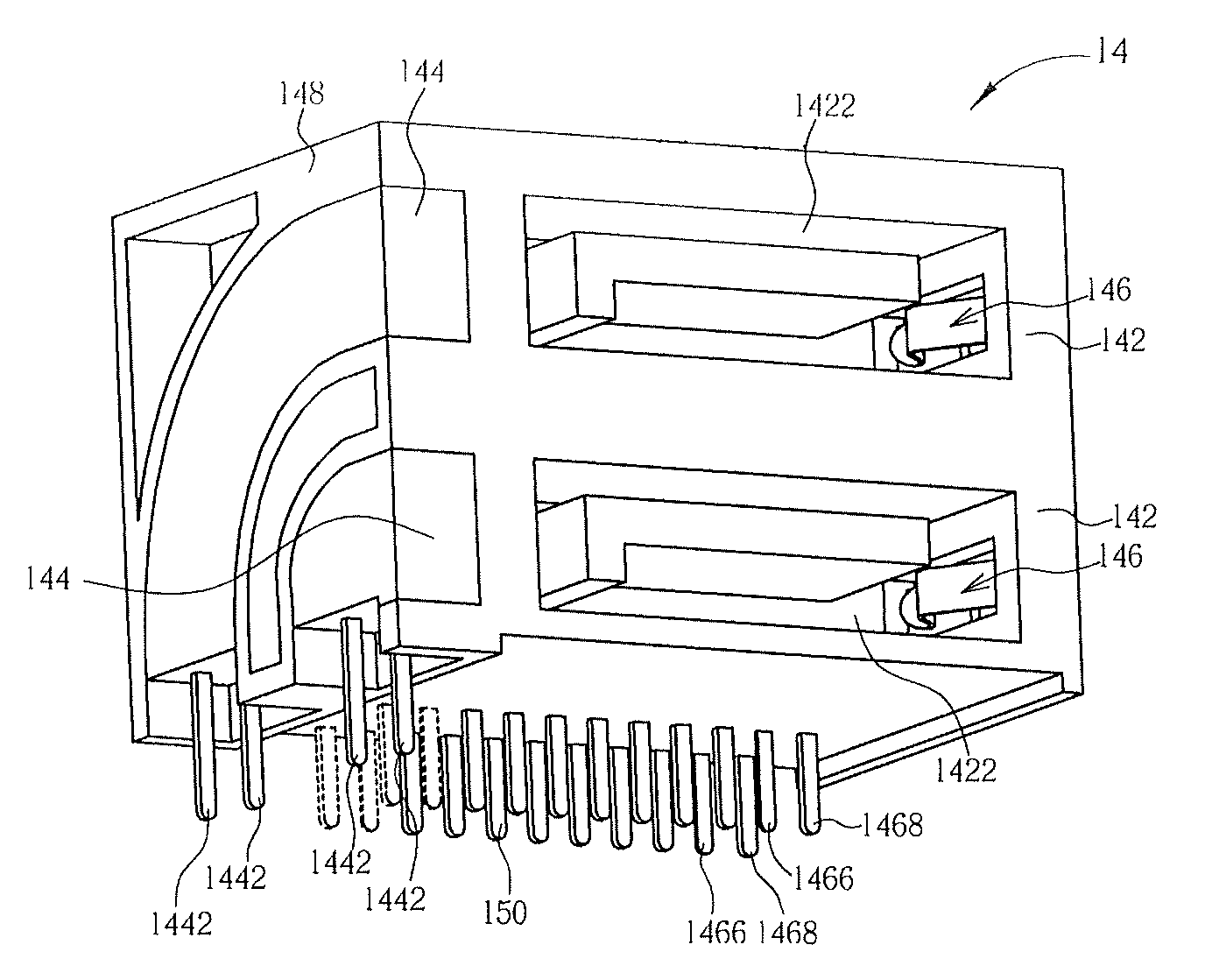
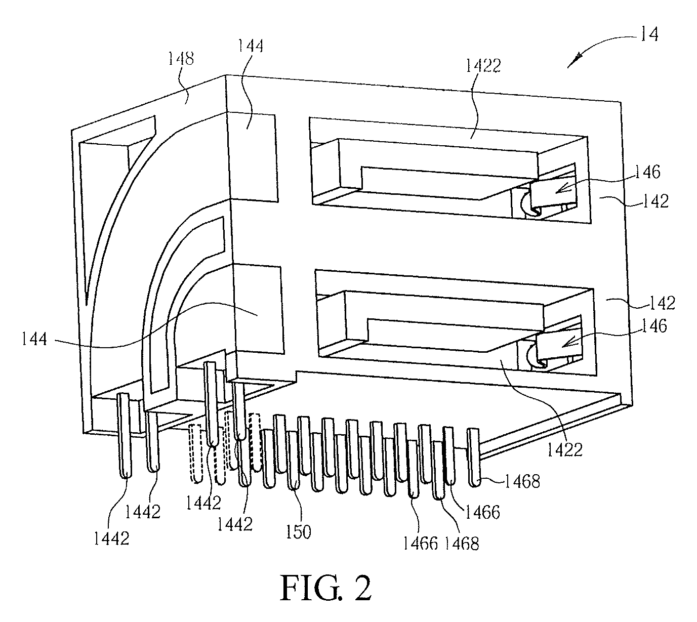
[0023]FIG. 2 is a three-dimensional diagram showing the connecting modules 14. FIG. 3 is a front view diagram showing the connecting module 14 in FIG. 2. FIG. 4 is a sectional diagram showing the connecting module 14 i...

second embodiment

[0025]In the embodiment of the invention, the switch 146 is disposed at the right side of the accommodating space 1422, but the invention is not limited thereto. For example, the switch 146 also may be disposed at the left side of the accommodating space 1422, and similarly, the elastic portion 1462 extends from the left side wall 1424 to the accommodating space 1422, which is shown as the dashed line in FIG. 3 and FIG. 4. As shown in FIG. 6, it is a sectional diagram showing the connecting module 14 taken along a line whose position is the same as the line Y-Y in FIG. 3 in the invention. In FIG. 6, the switch 146 is disposed at the bottom wall 1425 of the accommodating space 1422, and the elastic portion 1462 extends from the bottom wall 1426 to the accommodating space 1422. Similarly, after the plug 32 is inserted into the accommodating space 1422, the front portion of the plug 32 presses the elastic portion 1462 to contact the contacting portion 1464, and the switch 146 is also c...

third embodiment

[0027]In the above embodiment, the optical indicator 144 directly disposed adjacent to the first connector (near the opening of the accommodating space 1422) can directly indicate the needed first connector. To the sequentially arranged first connectors, if the corresponding optical indicators are also disposed sequentially, the user also may get the position of the needed connecting module according to the position of the optical indicator. As shown in FIG. 8 and FIG. 9, FIG. 8 is a three-dimensional diagram showing a connecting module 14 according to the invention, and FIG. 9 is a sectional diagram showing the first connector taken along a line whose position is the same as the line Y-Y in FIG. 3. The difference between FIG. 9 and FIG. 2 is that the optical indicators 144 are arranged on the housing 148 adjacently, and preferably located at the top wall of the housing 148 to allow the user to identify quickly. In addition, in the embodiment, the elastic portion 1462 of the switch ...


PUM


Abstract

A connecting module with optical indication for being disposed on an electronic device is disclosed. The connecting module includes multiple first connectors disposed adjacently, and each first connector includes a base, a switch and an optical indicator. The base has an accommodating space, and the switch is disposed at a side wall of the accommodating space. When a second connector is connected to the first connector, a plug of the second connector is inserted into the accommodating space and triggers the switch so as to enable the optical indicator for indicating a connection status of the first connector.

Description

CROSS REFERENCE TO RELATED APPLICATIONS[0001]This application claims the benefit of U.S. Provisional Application No. 61 / 233,487, filed on Aug. 12, 2009 and entitled “MOTHERBOARD HAVING DISPLAY DEVICE WITH INDICATION MECHANISM” the contents of which are incorporated herein.BACKGROUND OF THE INVENTION[0002]1. Field of the Invention[0003]The invention relates to a connecting module disposed on an electronic device and, more particularly, to a connecting module with a optical indication.[0004]2. Description of the Related Art[0005]Nowadays, an electronic device usually has multiple connecting modules to facilitate expansion. In a small system such as a personal computer with connecting modules of the same type, the user may identify the needed connecting modules according to the appearance of the corresponding device. However, if multiple devices with the same type are connected to connecting modules with the same type, and the connecting modules are arranged close to each other, the us...

Claims


Application Information

Patent Timeline
Patent Type & Authority Patents(United States)
IPC IPC(8): H01R3/00
CPCH01R13/641H01R12/724H01R13/7175H01R13/703H01R25/006
Inventor WU, CHAO-CHUNGCHIU, KUO-CHOU
Owner ASUSTEK COMPUTER INC
Why Eureka
Try Eureka