Imaging apparatus and HDRI method

a technology of hdri and image, applied in the field of hdri image and image, can solve the problem of inability to adjust the positions of each part of the two images, and achieve the effect of improving the quality of the imag

Active Publication Date: 2012-11-06
RICOH IMAGING COMPANY
View PDF22 Cites 14 Cited by
  • Summary
  • Abstract
  • Description
  • Claims
  • Application Information

AI Technical Summary

Benefits of technology

[0006]An aspect of the present invention is to provide an imaging apparatus and an HDRI method that are able to adjust displacement of images, which are captured in bracketing, by minimizing displacement of a main photographing object.

Problems solved by technology

When any two images captured in any bracketing are shot at different settings, i.e., at different positions or angles, it is impossible to adjust the positions of every part of the two images in an image composition because the two images include parallax and the like.
This situation may occur when image-capturing operations are carried out in unstable conditions, such as hand-held shooting.

Method used


Image

  • Imaging apparatus and HDRI method
  • Imaging apparatus and HDRI method
  • Imaging apparatus and HDRI method

Examples


Embodiment Construction

[0014]The present invention is described below with reference to the embodiments shown in the drawings.

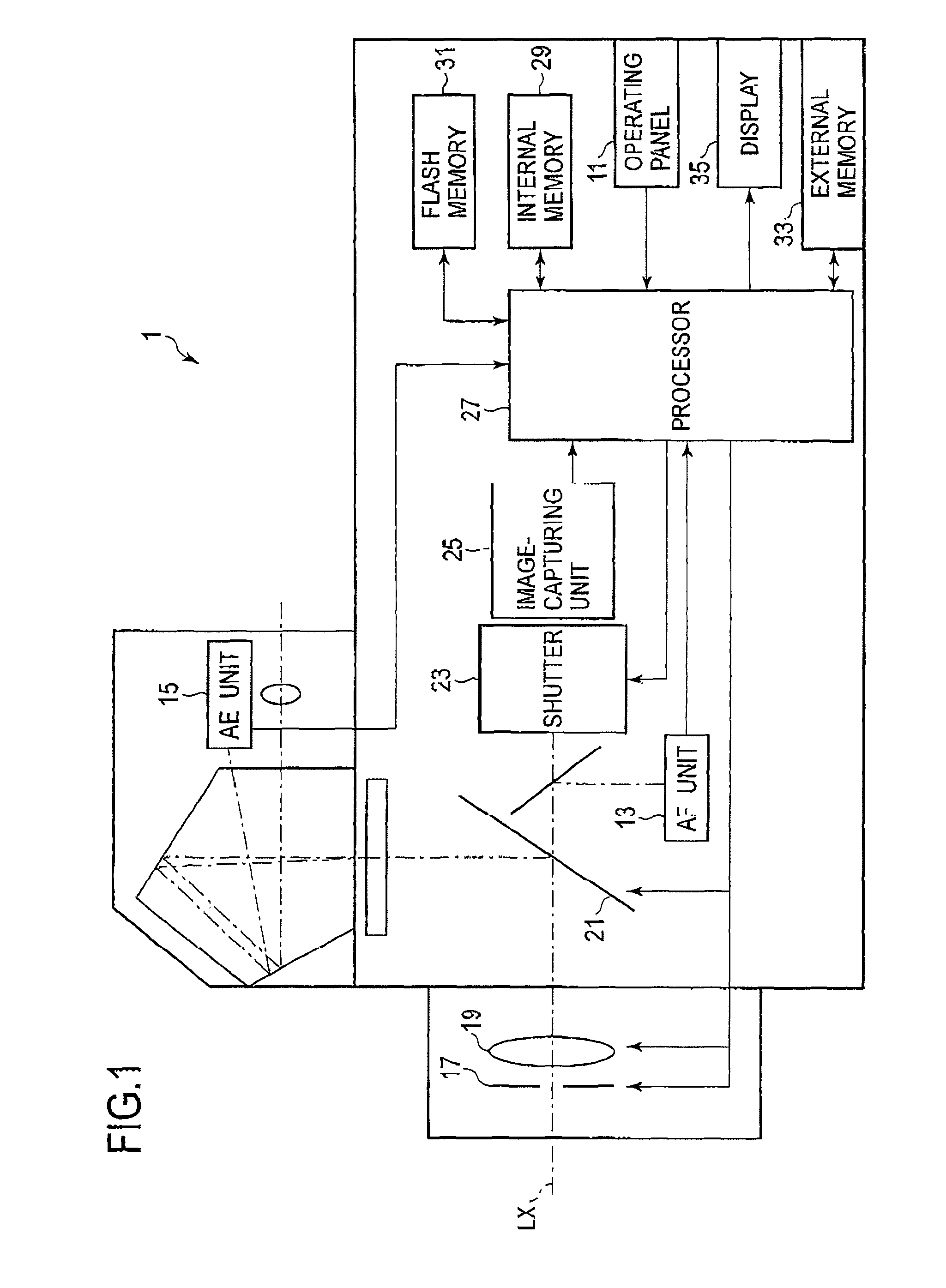
[0015]FIG. 1 is a block diagram schematically illustrating the general structure of an imaging apparatus 1 of an embodiment of the present invention. The imaging apparatus 1 may be a digital camera having a operating panel 11, an AF (autofocus) unit 13, au AE (auto exposure) unit 15, a stop 17, a lens 19, a mirror 21, a shutter 23, an image-capturing unit 25 including an image sensor such as a CCD or CMOS, a processor 27 such as a DSP and / or CPU, an internal memory 29, a flash memory 31, an external memory 33, and a display 35.

[0016]The operating panel 11 includes a release button and a mode-select key (not depicted). When the release button is half depressed, a photometry switch is activated and the AF unit 13 carries out a distance measurement while the AE unit carries out photometry. The result of the distance measurement may be fed into the processor 27 from the AF unit 13 to c...


PUM


Abstract

An imaging apparatus includes an image sensor and a processor that merges together a plurality of images captured by said image sensor to produce a composite image. The positions or the plurality of images being adjusted to reduce displacement of a reference area that is determined within each one of said plurality of images before the plurality of images is merged together. The reference area includes at least one of an in-focus area determined by a focusing operation, a face area determined by face-sensing processes, a predetermined-color area determined by white-balance information and predetermined color information, and a predetermined-brightness area determined by photometry.

Description

BACKGROUND OF THE INVENTION[0001]1. Field of the Invention[0002]The present invention relates to an apparatus and method for merging together a plurality of images. In particular, an apparatus and method that merge together images to produce a composite image having a wide dynamic range of luminance may be referred to as high dynamic range imaging (HDRI).[0003]2. Description of the Related Art[0004]Conventionally, a set of high dynamic range imaging techniques is provided that merges together a plurality of photographic images captured under different exposure parameters or values (i.e., under exposure bracketing) in order to generate an image having a wider dynamic range of luminance.SUMMARY OF THE INVENTION[0005]When any two images captured in any bracketing are shot at different settings, i.e., at different positions or angles, it is impossible to adjust the positions of every part of the two images in an image composition because the two images include parallax and the like. Thi...

Claims


Application Information

Patent Timeline
Patent Type & Authority Patents(United States)
IPC IPC(8): H04N5/228G06K9/32H04N5/262H04N5/243H04N5/335H04N5/355H04N9/04
CPCH04N5/23219H04N5/23229H04N5/23248H04N5/23254H04N5/235H04N5/2355H04N23/611H04N23/80H04N23/6811H04N23/68H04N23/70H04N23/741
Inventor TERAUCHI, MASAKAZU
Owner RICOH IMAGING COMPANY
Why Eureka
Try Eureka