[0018]In some embodiments, in the proximal portion of the stem, the
medial surface dimension or measure (e.g., a
transverse dimension) taken in a first plane perpendicular to the longitudinal axis of the implant comprises a dimension or measure 5% to 100%, or more, greater than the lateral surface measure in the same plane and, in the
distal portion of the stem, the lateral surface taken in a second plane perpendicular to the longitudinal axis of the implant comprises a dimension or measure 5% to 100%, or more, greater than the
medial surface dimension measure taken in the same plane. This results in large
load bearing areas on the wide
medial surface proximally and on the wide lateral surface distally. This also promotes self-centering of the implant in the medullary canal, avoiding varus or valgus mal-alignment.
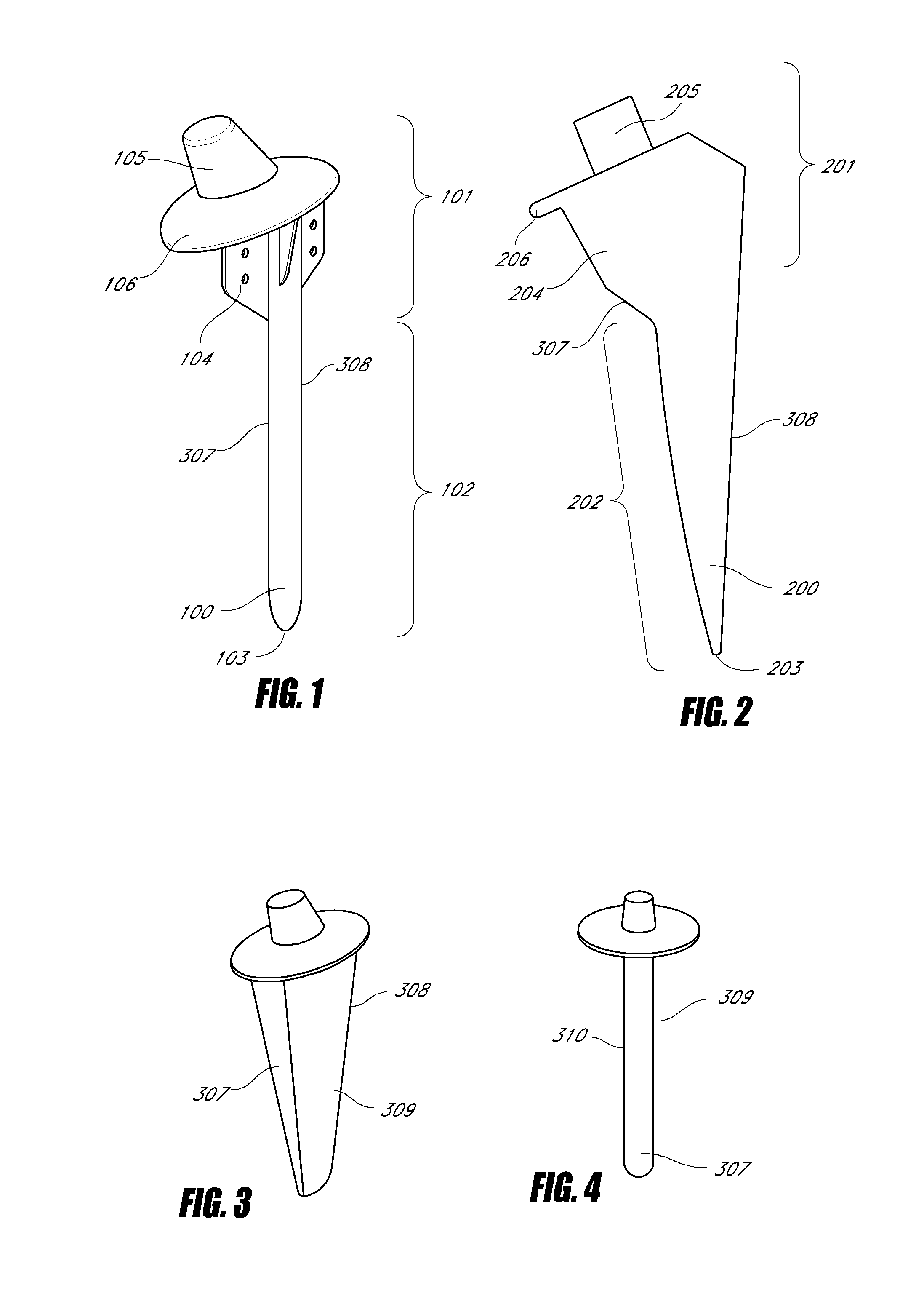
[0019]In one embodiment of the invention, the implant is a femoral implant for use in
hip arthroplasty. In some embodiments, the implant has one, two, three, four, or more axially oriented protrusions on the
anterior surface, posterior surface, or both, which act, during implantation, as guide rails. In some embodiments, there are relatively medial and lateral guide rails on the anterior and posterior surfaces. In some embodiments of the invention, the medial guide rail extends further distally than the lateral guide rail, the lateral guide rail extends further distally than the medial guide rail, or they can extend the substantially same distance. The guide rails can serve multiple purposes. They help guide the implant during
insertion, prevent rotation of the implant during and after
insertion, and provide spaces between the rails for compacted
cancellous bone, which increases the stability of the inserted implant. In another embodiment of the femoral implant, there are one, two, three or more voids on the proximal portion of the implant on the
anterior surface, posterior surface, or both. These voids may be round, or any appropriate shape. The voids accommodate compressed
cancellous bone during
insertion or accommodate
bone cement dispensed to assist fixation of the implant. In other embodiments, there are no voids.
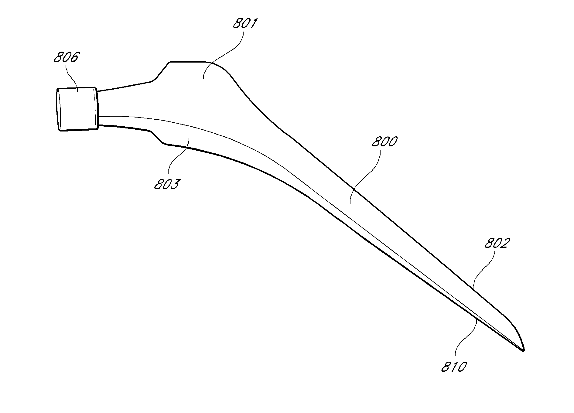
[0020]In a further embodiment of the femoral implant, there is a lateral
keel. Where the lateral
keel arises on the proximal portion of the implant, there is a localized reduction in the cross section of the implant, when compared to adjacent sections of the
keel laterally and stem medially. This allows minimized displacement of
cancellous bone during insertion, reducing forces during insertion and also resists rotation of the implant both during and after insertion. In other embodiments, there is no lateral keel, or a keel without localized reduced cross section of the implant. In some embodiments, the length of the femoral implant is 100 to 130 mm. In other embodiments, it may be less than 100 mm or more than 130 mm.
[0021]In a further embodiment, the implant is a humeral implant for use in shoulder
arthroplasty. In some embodiments, the implant has one, two, three, four or more stabilization ribs which provide mechanical structure,
resist rotation of the implant within the bone, and enhance stability of the implant within the bone after implantation. In some embodiments, the ribs are on the
anterior surface, posterior surface, or anterior and posterior surfaces. In other embodiments, there is a stabilization fin on the lateral aspect of the proximal surface. In some embodiments of the invention, the implant includes a collar proximally to rest on the
cortical bone and prevent
subsidence of the implant into the
humerus after implantation. In other embodiments, there is no collar. In some embodiments the implant has an overall length of 70 to 90 mm. In other embodiments, the implant has a length less than 70 mm, preferably about 60 mm. In some embodiments of the invention, the medial and lateral surfaces of the implant are curved, e.g., arcuate longitudinally. In other embodiments, the medial surface is arcuate, while the lateral surface is straight, or having an axis that is parallel or substantially parallel to a central longitudinal axis of the implant. In still other embodiments, neither the medial nor lateral surface is curved, e.g., arcuate along the length of the implant.
[0028]Another aspect of the invention features a
minimal incision shoulder
arthroplasty technique that allows replacement of the glenoid surface and humeral head with only a
small incision and less extensive
soft tissue stripping. The “mini-incision” procedure also leaves the pectoralis
tendon and the majority of the inferior
capsule intact. The advantages of the “mini-incision” procedure include a shorter incision with less scarring, increased safety, and a more simple exposure of the glenoid, thus allowing general orthopedists to perform a shoulder replacement with less difficulty and potentially fewer complications. The
skin incision is preferably less than 10 cm. in length, more preferably between 7 and 10 cm.

