Roof mirror assembly

a technology for roof mirrors and assemblies, applied in the field of retroreflectors, can solve problems such as the loss of accuracy of retroreflectors when exposed to external stresses

Inactive Publication Date: 2007-01-30
PLX
View PDF31 Cites 18 Cited by
  • Summary
  • Abstract
  • Description
  • Claims
  • Application Information

AI Technical Summary

Benefits of technology

[0015]In addition, the roof mirror assembly and the mirror panel mounting are, in a preferred embodiment, kinematic structures that are also improvements over earlier constructions. In particular, the roof mirror assembly of the subject invention has, in a preferred, but not required, embodiment, at least a pair of mounting blocks that act also as back supports and are located substantially at opposite ends of the roof mirror. However, the invention also anticipates the roof mirror assembly having only at least one mounting member. The manner of attachment of the mounting blocks to the back portions of the mirror panels making up the roof mirror assembly, is such that expansion and contraction of the reflective surfaces of the mirror panels of the roof mirror assembly will be in a direction substantially perpendicular to the direction of the roof angle axis. Deflection in this direction helps to minimize displacement (error) of the transmitted light beam traveling through the lateral transfer retroreflector. Similarly, the mounting of the mirror panel to the mirror panel housing by means of substantially 45° chamfered edges, insures that the forces exerted by thermal expansion or contraction of the bonding material situated along those chamfered edges, will have a canceling effect, and not deflect the reflective surface of the mirror panel.
[0016]Accordingly, it is an object of the present invention to provide an improved lateral transfer retroreflector assembly and an improved roof mirror assembly.
[0017]Still another object of the invention is to provide a lateral transfer retroreflector assembly having a component construction capable of allowing for off-the-shelf customization for different customer needs based upon differing customer specifications.
[0018]Yet a further object of the invention is to provide a lateral transfer retroreflector assembly having a roof mirror assembly construction and mounting such that deformations in the reflective surfaces of the mirror panels of the roof mirror assembly due to thermal expansion / contraction are minimized in the direction of the roof angle axis.
[0019]A still further object of the invention is to provide a lateral transfer retroreflector assembly, wherein the deflective forces exerted on the mirror panel by thermal expansion or contraction of the joint bonding the mirror panel to the mirror panel housing, are minimized.

Problems solved by technology

Retroreflectors lose accuracy when they are exposed to external stresses.

Method used


Image

  • Roof mirror assembly
  • Roof mirror assembly
  • Roof mirror assembly

Examples


Embodiment Construction

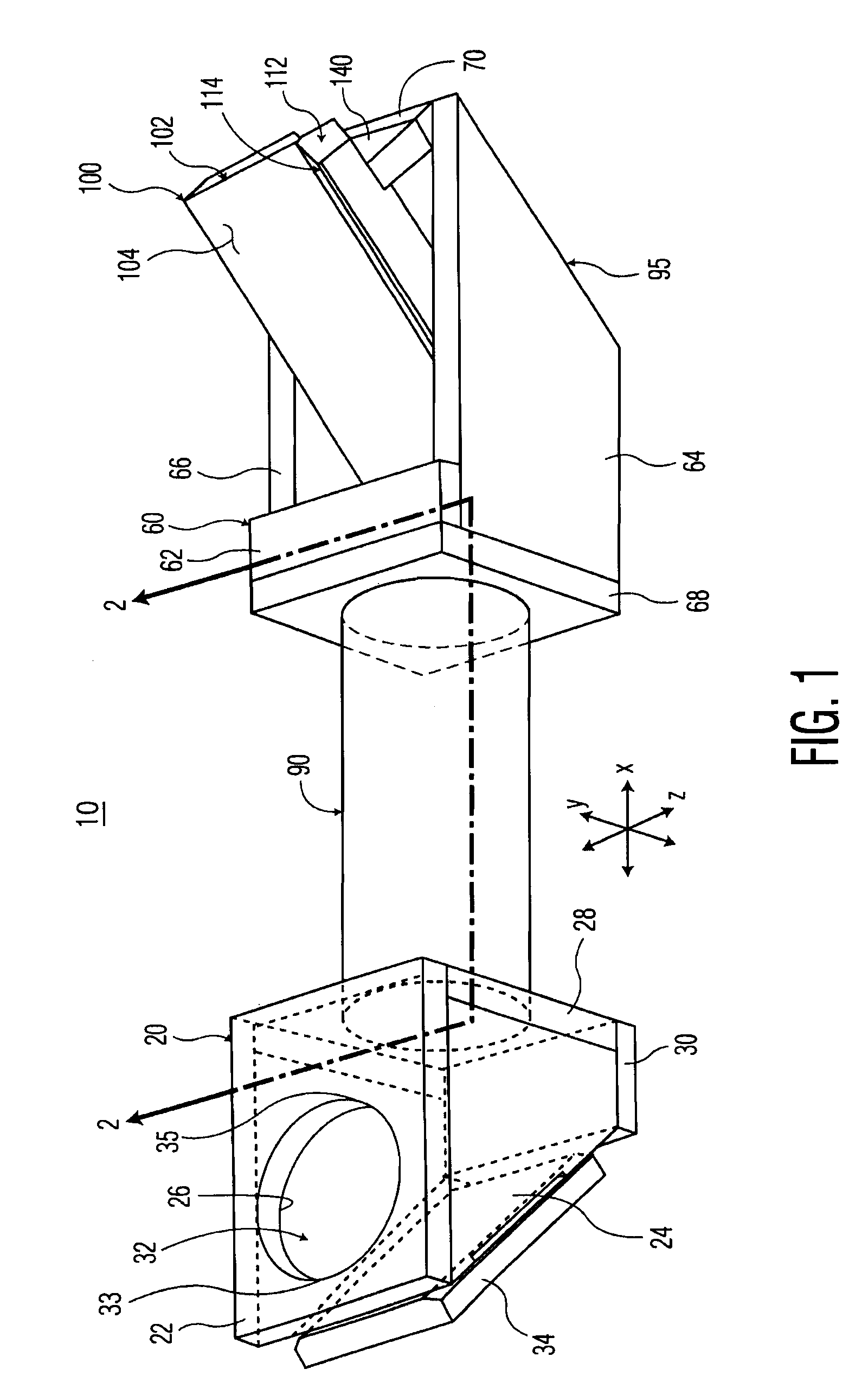
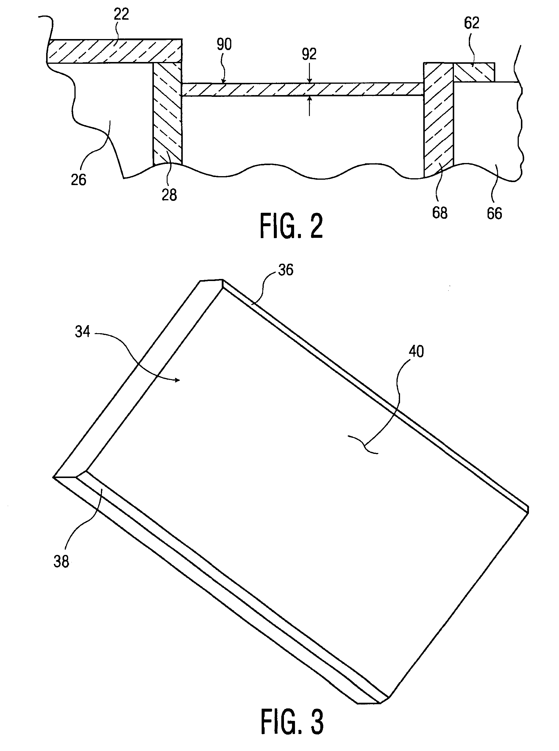
[0043]Referring to FIG. 1, a lateral transfer retroreflector assembly made in accordance with the invention and generally designated at 10, is illustrated. Lateral Transfer Retroreflector (“LTR”) 10 comprises three components; a mirror panel housing 20, a roof mirror assembly housing 60 and a connecting member 90, having a thickness 92.

[0044]As seen in FIGS. 1 and 4, mirror panel housing 20 is comprised of first and second side members 24 and 26, as well as receiving member 28, for receiving connecting member 90. Housing 20 can also include member 30, to lend extra stability to the structure, as well as aperture receiving member 22, having aperture 32 extending therethrough. Aperture 32 can be of any geometric configuration, the preferred configurations being in the circle and square families. Aperture 32 has a first end 33 and a second end 35, the distance between which will help dictate the inside diameter of connecting member 90. It is to be understood herein that member 90 does ...


PUM


Abstract

An improved roof mirror assembly is provided. The roof mirror assembly of the invention is comprised of first and second mirror panels comprising first and second reflective surfaces and first and second mounting surfaces, respectively, the first and second mirror panels being joined together so that the first and second reflective surfaces are substantially perpendicular to each other. The assembly further comprising at least one mounting block comprising at least one opening extending through a portion thereof and at least one mounting pin received within the at least one opening of the at least one mounting block, wherein the at least one mounting pin is attached within the opening to the at least one mounting block and is attached to at least one of the first or second mounting surfaces of the first or second mirror panels. In an embodiment not having the mounting pins, the mirror panels each comprise first and second ends, wherein the first ends of the mirror panels are proximate to each other and the second ends of the mirror panels are proximate to each other when the mirror panels are in their joined condition, and the at least one mounting block is attached to the first ends of the mirror panels, and the assembly is mounted onto another structure along a bottom surface of the at least one mounting block.

Description

[0001]This application is a continuation-in-part of application Ser. No. 09 / 894,207, filed Jun. 28, 2001, issued May 4, 2004 as U.S. Pat. No. 6,729,735, which application is hereby incorporated by reference herein in its entirety.BACKGROUND OF THE INVENTION[0002]This invention relates to the field of retroreflectors, and more particularly, to lateral transfer retroreflectors and roof mirror assemblies.[0003]Retroreflectors generally have the property of causing incident and reflected light rays to travel along parallel paths. To achieve this parallelism, a retroreflector normally consists of three optically flat reflecting surfaces, each reflecting surface positioned at a right angle to each of the other reflecting surfaces. Any departure of the reflecting surfaces from their perpendicular orientation will cause the incident and reflected light rays to depart from parallel.[0004]Retroreflectors lose accuracy when they are exposed to external stresses. Examples of such external stres...

Claims


Application Information

Patent Timeline
Patent Type & Authority Patents(United States)
IPC IPC(8): G02B5/08G02B7/182G02B5/12
CPCG02B5/12
Inventor BLEIER, ZVIVISHNIA, ITAI
Owner PLX
Why Eureka
Try Eureka