Shock-limiting interface, compact (SLIC)

a compact, shock-limiting technology, applied in the direction of machine supports, transportation and packaging, other domestic objects, etc., can solve the problems of significant vertical shocks of planing boats operating in rough water, serious injuries, roll stability problems,

Inactive Publication Date: 2007-02-15
STENARD JOHN
View PDF62 Cites 18 Cited by
  • Summary
  • Abstract
  • Description
  • Claims
  • Application Information

AI Technical Summary

Benefits of technology

[0016] The second principle is that the displacement required to dissipate the shock energy be minimized.
[0021] (1) The Frame Assembly (FA) mounts directly to the vehicle. It provides structural support to the other major assemblies, constraining their movement to within acceptable-limits, and enabling them to function properly.
[0028] The limiting interface may optionally include an anticipating assembly disposed between the frame assembly and the payload interface assembly that repositions the payload interface assembly relative to the structure from a neutral position in anticipation of an event. In one such embodiment, the anticipating assembly increases a range of travel of the payload interface assembly relative to the structure in anticipation of an event.

Problems solved by technology

Planing boats operating in rough water may experience significant vertical shocks when the boat and wave impact one another.
Shock impulses on the order of 50 Gs with pulse durations in excess of 40 milliseconds are not uncommon, and such shock is more than enough to cause serious injury.
But deep-vee hulls require deeper water for safe navigation, may have roll stability issues, and generally require more fuel for a given speed than shallow-vee hulls.
Moreover, they cannot unquestionably limit the acceleration on the Payload in all cases of boat-water impact.
The drawback of these approaches is the speed reduction.
Military and law-enforcement boats often cannot slow too much without risking mission failure.
Perhaps the most serious drawback of previous approaches is that they cannot protect the Payload if the incident shock peak or its rate of rise is too large.
But the performance of these same deices degrades as the rate of rise and / or peak amplitude of the acceleration increases.
A problem related to protection from boat shock is protection from explosive shock.
Explosions have such short pulse durations, as small as a fraction of a millisecond, that an active protection system would require an extremely high sampling rate, some very rapid processing algorithms to discriminate between noise and an actual explosion, and very rapid actuators to effect protection of the Payload, making an active protection system very expensive, if it could be made at all.
Current approaches using passive viscous damping systems would either break or dump fluid out their relief valve under such extreme forces.
Hardening generally results in increased weight and volume, and often impacts accessibility for maintenance and convective cooling.
Resilient mounting often exacts volume penalty in order to accommodate sway and surge of the equipment during shock.
No systematic, engineered approach which can unequivocally protect a Payload from explosive shock has been developed.
Another drawback of many previous approaches is an inability to adjust to the weights of various Payloads.
These devices are either overly stiff or overly soft depending upon the Payload mass.
Overly stiff devices obviously transmit too much force to the Payload.
But overly soft devices may also be inadequate in that they expend all available relative displacement between Payload and vehicle without absorbing all the shock energy.
Even if the Payload does not bottom out, an overly soft interface takes up more volume than required, impacting its usefulness, particularly in high-performance vehicles.
A further drawback of previous devices is a slow reset time.
If the device cannot restore the Payload to its original position before the next shock hits, then the next shock may cause it to bottom out.

Method used


Image

  • Shock-limiting interface, compact (SLIC)
  • Shock-limiting interface, compact (SLIC)
  • Shock-limiting interface, compact (SLIC)

Examples


embodiment

Concepts of Embodiment

[0060] A number of useful shock-limiting applications are conceived. The invention has applications for protecting a Payload housed in a structure as well as a Payload riding in a vehicle. Various seating systems, equipment foundations, cockpits, standing, platforms, even entire chambers can be isolated from their host vehicle or their other surroundings. The invention can also be implemented on the exterior of a vehicle, as a shock-limiting bumper to reduce the impact force of a head-on collision. The invention could be installed on the exterior of a fixed structure, such a bridge abutment, to limit the force on the structure which may result from accidental vehicle impact. An amusement park thrill ride offering a vertical free-fail of several hundred feet and “a sudden” thrill stop at the end could be implemented. Another application is as a bumper system on the front end of a vehicle

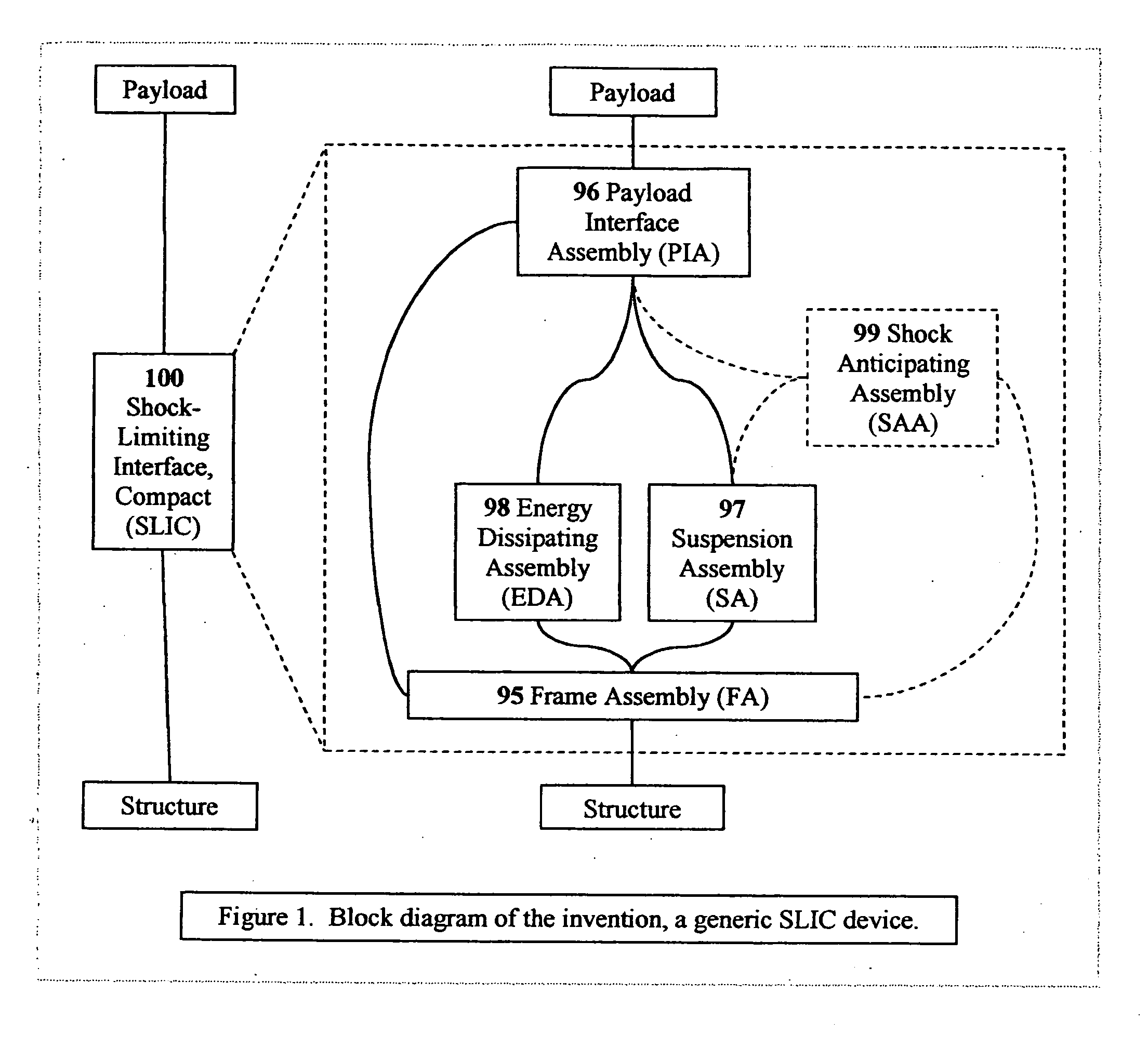
[0061]FIG. 1 shows a block diagram of a SLIC device 100 mounted functionall...


PUM


Abstract

A passive / reactive device protests a Payload from injury or damage due to the shock caused by impact or explosion. When the vehicle or structure mounting the Payload receives a shock pulse, the invention limits the acceleration transmitted from the vehicle or structure to the Payload to an acceptably low, user-adjustable level which is substantially constant or is some other user-adjustable force-displacement function. The invention is capable of doing so even when the peak magnitude of the imposed shock is on the order of thousands of G's, with a rise time to peak on the order of microseconds. The invention can be embodied to operate passively, without any external source of power, sensor system, or CPU, although they can be added to improve certain usability features. The invention also absorbs or dissipates the shock energy in substantially the minimum distance possible without exceeding the user-defined acceleration limit on the Payload. The invention can also react when a shock-producing impact is imminent by repositioning the Payload away from the impact site. The Payload can be a person or persons, or shock-vulnerable equipment. The shock can be created in a number of ways, including an explosion, an impact or collision, the slamming on high-performance boats and some off-road vehicles, earthquake, or even intentional shocks on an amusement thrill ride. The ability of the invention to protect against shock is limited only by its ability to absorb or dissipate the energy of the shock pulse on the Payload. The device can be implemented to protect against shock from any arbitrary direction. The name Shock-Limiting Interface, Compact (SLIC) is coined for this invention.

Description

[0001] The present invention claims the priority of Provisional Patent Application 60 / 345,275 filed Jan. 2, 2002, and Provisional Patent Application 60 / 402,522 filed Aug. 9, 2002, the disclosures of which are incorporated herein by reference in their entireties.[0002] The present invention is a new concept in protecting a Payload from injury or damage due to the shock of impact experienced by the Payload's vehicle (or structure). The present invention is installed as an interface between the Payload and vehicle; and limits the force transmitted to the Payload while absorbing the energy of the shock pulse. The invention can be embodied in many ways, including as a seating system, a passenger platform, an equipment mounting system, a crash protection capsule, a blast-proof chamber, or a thrill ride. [0003] The invention is unusually adept at protecting against shock. Unlike other shock-absorbing approaches which reduce the transmitted shock to a percentage of the excitation shock, thi...

Claims


Application Information

Patent Timeline
Patent Type & Authority Applications(United States)
IPC IPC(8): F16M13/00
CPCB60N2/4242B60N2/42736B60N2/4279B60N2/501B60N2/544B60N2/505B60N2/507B60N2/522B60N2/525B60N2/502
Inventor STENARD, JOHN KEVIN
Owner STENARD JOHN
Why Eureka
Try Eureka