
Ore pulp flow control and adjustment valve and control method thereof

A flow control and regulating valve technology, applied in the field of regulating valves, to achieve the effect of eliminating high-speed impact factors

Active Publication Date: 2016-07-13
湖南中工矿业工程技术有限公司
View PDF8 Cites 3 Cited by
  • Summary
  • Abstract
  • Description
  • Claims
  • Application Information

AI Technical Summary

Problems solved by technology

Although these wear-resistant valves have improved the service life of the slurry control valve to a certain extent, they still fail to solve the problem for users

Method used


Image

  • Ore pulp flow control and adjustment valve and control method thereof

Examples


Embodiment Construction

[0026] Embodiments of the present invention will be described in detail below in conjunction with the accompanying drawings.

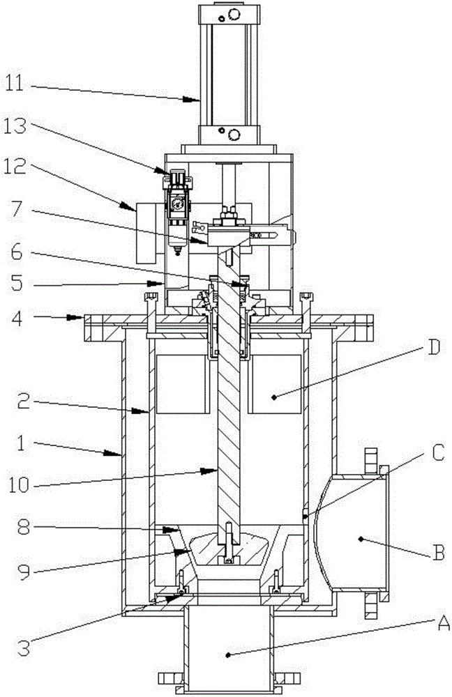
[0027] see figure 1 , The present invention provides a pulp flow control regulating valve, comprising a valve outer cylinder 1, a valve cover plate 4, a cylinder bracket 5, a bushing 6, a valve seat 8, a valve shaft 10, a valve core 9, a cylinder 11 and a valve inner cylinder 2 .

[0028] The bottom end of the valve outer cylinder 1 is provided with a pulp inlet A, the side is provided with a pulp outlet B, and a flange is welded on the upper end; the pulp inlet A is connected to the pulp incoming end with a pipeline, and the pulp outlet B is connected to the pulp discharge port. end pipe connection.

[0029] The valve cover plate 4 is fixed on the upper end of the valve outer cylinder 1 through the flange, and the cylinder bracket 5 and the shaft sleeve 6 are fixed on the valve cover plate 4 .

[0030] The valve inner cylinder 2 is arranged inside ...


PUM


Abstract

The invention discloses an ore pulp flow control and adjustment valve and a control method thereof. The ore pulp flow control and adjustment valve comprises an outer valve barrel, a valve cover plate, a cylinder bracket, a shaft sleeve, a valve seat, a valve shaft, a valve core, a cylinder and an inner valve barrel, wherein the inner valve barrel is arranged in the outer valve barrel, and is matched with the outer valve barrel through pressing bolts; an ore pulp overflow opening is formed in the upper end of the inner valve barrel. An ore pulp storage device, namely the inner valve barrel, is arranged in the outer valve barrel, so that ore pulp jetted from a gap between the valve core and the valve seat can only act on ore pulp stored in the inner valve barrel, and the stored ore pulp is used for counteracting the impact energy of sequentially jetted ore pulp; therefore, direct action of the impact energy generated by ore pulp jetting on a valve body is avoided, and the service life of the ore pulp flow control and adjustment valve is finally prolonged.

Description

technical field [0001] The invention relates to a regulating valve, in particular to a pulp flow control regulating valve and a control method thereof. Background technique [0002] No matter the water valve, air valve, slurry valve or other regulating valves have a common feature, that is: in the working state, when the opening of the valve becomes smaller, the fluid velocity passing through the valve outer cylinder will increase significantly, and the scouring energy of the liquid will increase significantly. It will also increase significantly, which will cause greater impact and wear on the valve body, affecting the service life of the regulating valve. For the use of regulating valves, it is an industry consensus that "it cannot be used with a small opening for a long time". As for the slurry control valve, the situation is even more severe. [0003] First of all, due to the characteristics of the ore slurry, the slurry contains a large amount of high-hardness quartz ...

Claims


Application Information

Patent Timeline
IPC IPC(8): F16K1/32F16K27/02F16K47/02
CPCF16K1/32F16K27/02F16K47/023
Inventor 李安迎周介凡杜佳
Owner 湖南中工矿业工程技术有限公司
Learn More