Power-splitting broadband omnidirectional radiation antenna

An omnidirectional radiation and broadband technology, applied in the field of radiating antennas, can solve the problems of narrow operating frequency band, poor flexibility, and large space occupied by the antenna, and achieve the effect of improving the radiation direction, easy installation, and widening the frequency band.

Active Publication Date: 2012-07-25
HARBIN INST OF TECH
View PDF4 Cites 5 Cited by
  • Summary
  • Abstract
  • Description
  • Claims
  • Application Information

AI Technical Summary

Problems solved by technology

[0003] The purpose of the present invention is to provide a power division broadband omnidirectional radiation antenna to solve the problems that the existing antenna can only work in a single system due to its narrow operating frequency band and the antenna occupies a large space and has poor flexibility

Method used


Image

  • Power-splitting broadband omnidirectional radiation antenna
  • Power-splitting broadband omnidirectional radiation antenna
  • Power-splitting broadband omnidirectional radiation antenna

Examples


specific Embodiment approach 1

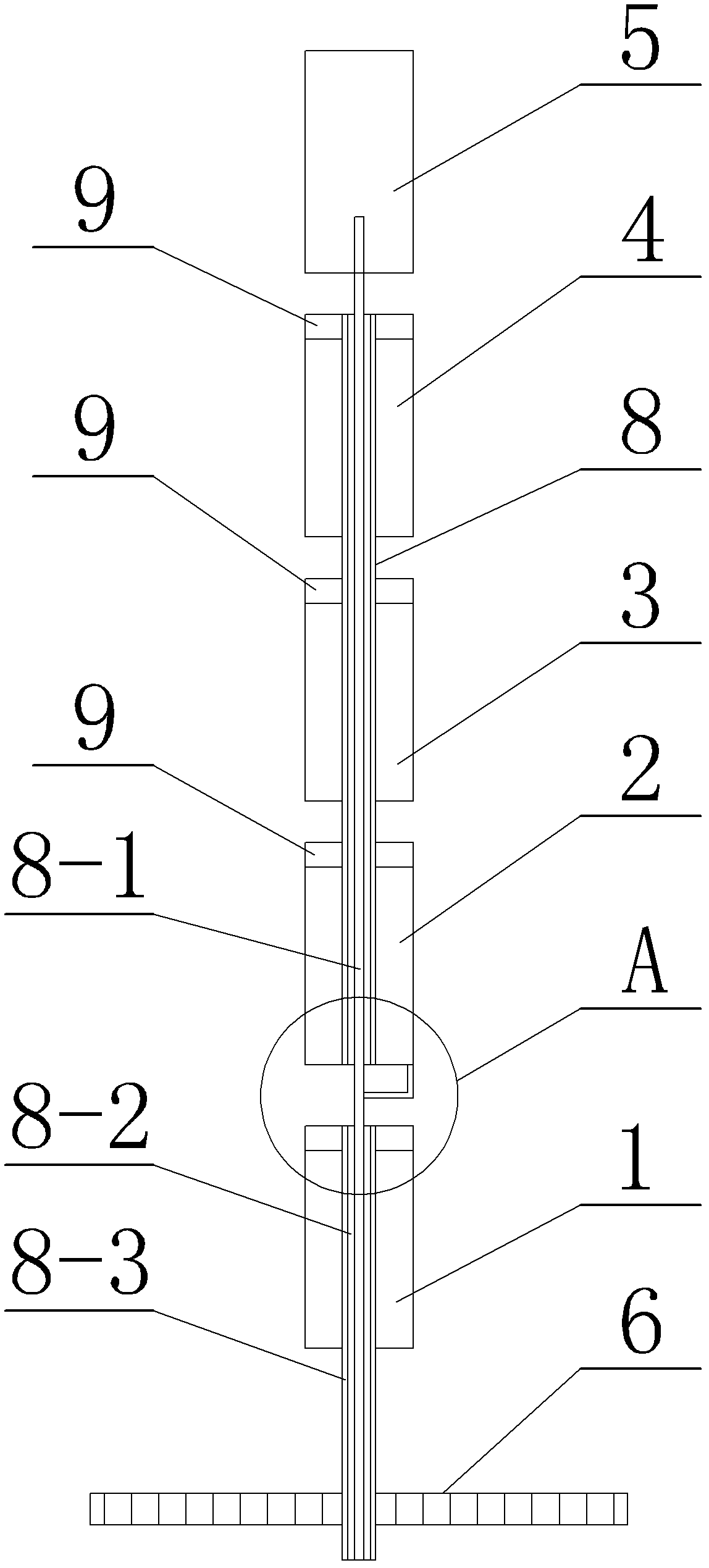
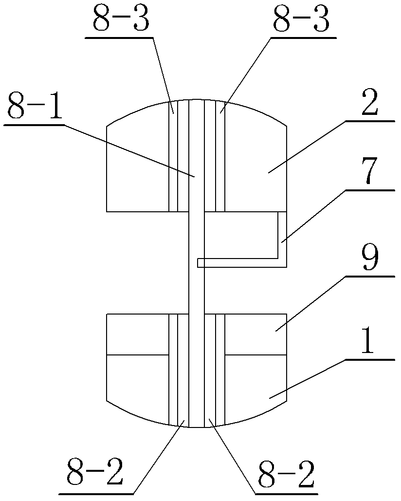
[0007] Specific implementation mode one: combine figure 1 , figure 2 with image 3 Describe this embodiment, the power division broadband omnidirectional radiation antenna described in this embodiment includes a coaxial line 8, and the coaxial line 8 is composed of a core wire 8-1, an insulating medium layer 8-2 and a shielding layer 8-3, The outer surface of the core wire 8-1 is wrapped with a layer of insulating medium layer 8-2, and the outer surface of the insulating medium layer 8-2 is wrapped with a layer of shielding layer 8-3. The power division broadband omnidirectional radiation antenna also includes a first metal Sleeve 1, second metal sleeve 2, choke sleeve 3, third metal sleeve 4, metal cylinder 5, metal disc 6, power dividing wire 7 and four metal sheets 9, the coaxial One end of 8 is fixedly connected to the center of the metal disc 6, and the other end of the coaxial line 8 passes through the first metal sleeve 1, the second metal sleeve 2, the choke sleeve ...

specific Embodiment approach 2

[0008] Specific implementation mode two: combination figure 1 with figure 2 Describe the distances between the second metal sleeve 2 and the choke sleeve 3, between the choke sleeve 3 and the third metal sleeve 4, and between the third metal sleeve 4 and the metal cylinder 5 in this embodiment Both are 2.5mm. This distance is set so that the second metal sleeve 2 , the choke sleeve 3 , the third metal sleeve 4 and the metal cylinder 5 have the best radiation effect of the emitted electromagnetic wave signal, and the connection relationship of other components is the same as that of the first embodiment.

specific Embodiment approach 3

[0009] Specific implementation mode three: combination figure 1 with figure 2 Explain that the distance between the first metal sleeve 1 and the second metal sleeve 2 in this embodiment is 3 millimeters. This distance is set so that the first metal sleeve 1 and the second metal sleeve 2 have the best radiation effect of the emitted electromagnetic wave signal, and the connection relationship of other components is the same as that of the specific embodiment 1 or 2.


PUM


Abstract

The invention relates to an antenna, in particular to a power-splitting broadband omnidirectional radiation antenna, which aims at solving the problems that the existing antenna can only work as a single system, the space occupied by the existing antenna is large and the flexibility is poor because the working frequency band of the existing antenna is narrower. One end of a coaxial line is fixedly connected with the center of a metal disc. The other end of the coaxial line sequentially penetrates through the centers of a first metal sleeve, a second metal sleeve, a choke sleeve and a third metal sleeve and is fixedly connected with the center of one end of a metal cylinder. The second metal sleeve, the choke sleeve, the third metal sleeve and the metal cylinder are equidistantly distributed on the coaxial line. One end of the first metal sleeve adjacent to the second metal sleeve, one end of the second metal sleeve adjacent to the choke sleeve, one end of the choke sleeve adjacent to the third metal sleeve and one end of the third metal sleeve adjacent to the metal cylinder are respectively and fixedly connected with a metal sheet. A power-splitting metal wire is arranged between the first metal sleeve and the second metal sleeve. The power-splitting broadband omnidirectional radiation antenna provided by the invention is used for transmitting electromagnetic wave signals.

Description

technical field [0001] The invention relates to a radiation antenna, in particular to a power division broadband omnidirectional radiation antenna. Background technique [0002] Existing rod-shaped antennas, such as COCO antennas, can only work with a single system due to their narrow operating frequency bands, and cannot cover multiple operating frequency bands. Installation, the problem of poor flexibility. Contents of the invention [0003] The purpose of the present invention is to provide a power division broadband omnidirectional radiation antenna to solve the problems that the existing antenna can only work with a single system due to its narrow operating frequency band, and the antenna occupies a large space and has poor flexibility. [0004] The technical solution adopted by the present invention to solve the above technical problems is: the power division broadband omnidirectional radiation antenna includes a coaxial line, the coaxial line is composed of a core ...

Claims


Application Information

Patent Timeline
Patent Type & Authority Applications(China)
IPC IPC(8): H01Q1/36H01Q1/52H01Q19/10
Inventor 张炀邱景辉特尼格尔郭文彬张鹏宇
Owner HARBIN INST OF TECH
Why Eureka
Try Eureka