Kinetic energy attenuation device and general classified highway fence using same

A technology for attenuation devices and highway guardrails, applied in road safety devices, roads, roads, etc., can solve problems such as hidden safety hazards, achieve low cost and maintenance costs, wide adaptability, and achieve major innovations and technological progress.

Inactive Publication Date: 2015-04-29
尚书 +1
View PDF8 Cites 4 Cited by
  • Summary
  • Abstract
  • Description
  • Claims
  • Application Information

AI Technical Summary

Problems solved by technology

If the protective performance of the guardrail is improved, its cost will also increase sharply. For example, the cost of the SBM semi-rigid guardrail is 680 yuan / m, while the cost of the SBM rigid guardrail is as high as 1050 yuan / m. Therefore, considering the factor of the project cost, the guardrail The design often has to lower the protection level and use SB-level (four-level) guardrails; for irrational vehicle accidents, it is entirely possible to have an impact above SB level, so there is a way to reduce product performance due to cost constraints. big security risk

Method used


Image

  • Kinetic energy attenuation device and general classified highway fence using same
  • Kinetic energy attenuation device and general classified highway fence using same
  • Kinetic energy attenuation device and general classified highway fence using same

Examples


Embodiment 1

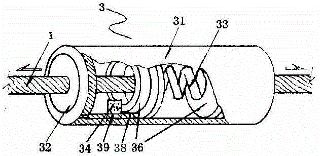
[0057] Such as Figure 1~5 As shown, a kinetic energy attenuation device 3 includes a hollow shell 31 with closed ends. The end covers 32 on both sides of the shell 31 are respectively provided with through holes for the rope 1 to pass through, and the two through holes are connected to the shell. The central axis is coaxial;

[0058] The casing 31 is cylindrical, and inner sleeves 39 are respectively embedded at both ends of the inner wall. The inner sleeve 39 fits closely with the inner wall of the casing. There is a gap between the inner sleeves 39 at both ends of the inner wall. An annular groove 35 is formed between the inner walls of the housing, and a stepped surface 38 is formed between the annular groove 35 and the inner sleeve 39, and the end covers 32 on both sides of the housing 31 are detachable;

[0059] The housing 31 is provided with a tension spring 33 capable of generating telescopic deformation and converting pressure into mechanical energy or thermal energy, th...

Embodiment 2

[0068] Such as Image 6 , Figure 7 As shown, the embodiment 1 is repeated, the difference is: the damaged body is a hollow destructible body 37 made of rigid material, and the hollow destructible body 37 is provided with a through hole for the rope 1 to pass through. The hollow damageable body 37 is placed in the cavity between the cylindrical pressing block 36 and the end caps 32 on both sides of the shell.


PUM


Abstract

The invention discloses a kinetic energy attenuation device, including a hollow shell with two closed ends, wherein a through hole through which a fence rope can pass is formed in the end face on each of two sides of the shell, and the two through holes are coaxial with the central axis of the shell; a movable damage device which is connected with the fence rope is arranged in the shell; a damage body is arranged between the damage device and each of the shell end cover, and a deformation body is arranged between the two damage device; when the fence rope is suddenly stressed, the damage device applies force to the damage bodies and the deformation body, the deformation body is stretched and the damage bodies are crushed, and thereby impact force suffered by the fence rope is converted into mechanical energy or thermal energy. Meanwhile, the invention also discloses a general classified highway fence using the kinetic energy attenuation device; through serially connecting kinetic energy attenuation devices applicable to low-frequency dynamic energy attenuation in the fence rope, the fence is good in energy attenuation effect; the parts are low in cost, so that the product cost is not increased by the promotion of the protection level; when in maintenance, the general classified highway fence only needs to replace the damage bodies simply, and is wider in adaptation and higher in reliability.

Description

Technical field [0001] The invention belongs to the technical field of highway safety protection, and specifically relates to a kinetic energy attenuation device and a general-grade highway guardrail using the device. Background technique [0002] Highway guardrail is an important safety facility to prevent safety accidents from passing out of the road or entering the opposite lane. There are three structural forms of highway guardrails currently in use: semi-rigid guardrails of corrugated steel plate structure, rigid guardrails of concrete structure and flexible guardrails of steel cable structure. Its technical characteristics are: rigid guardrails mainly rely on the climbing and steering of out-of-control vehicles to absorb collision energy; semi-rigid guardrails use the deformation of soil foundation, pillars, and corrugated steel plates to absorb collision energy and force out-of-control vehicles to change directions; Flexible guardrails rely on the tensile stress of cables...

Claims


Application Information

Patent Timeline
Patent Type & Authority Applications(China)
IPC IPC(8): E01F15/06
CPCE01F15/06E01F15/065
Inventor 尚久駜尚书
Owner 尚书
Why Eureka
Try Eureka