
Seat rail module for a vehicle seat for vehicle seat deceleration in the event of a crash

A technology for seat guide rails and vehicle seats, which is applied in the direction of vehicle seats, special positions of vehicles, movable seats, etc., can solve the problems of reduced effectiveness of the occupant restraint system, and achieve the effect of compact geometry

Active Publication Date: 2021-03-19
BROSE FAHRZEUGTEILE GMBH & CO KG
View PDF11 Cites 3 Cited by
  • Summary
  • Abstract
  • Description
  • Claims
  • Application Information

AI Technical Summary

Problems solved by technology

This in turn leads to extra distance and room to move in the event of a frontal or rear collision, resulting in a reduction in the effectiveness of the occupant restraint system, which is undesirable

Method used


Image

  • Seat rail module for a vehicle seat for vehicle seat deceleration in the event of a crash
  • Seat rail module for a vehicle seat for vehicle seat deceleration in the event of a crash
  • Seat rail module for a vehicle seat for vehicle seat deceleration in the event of a crash

Examples


Embodiment Construction

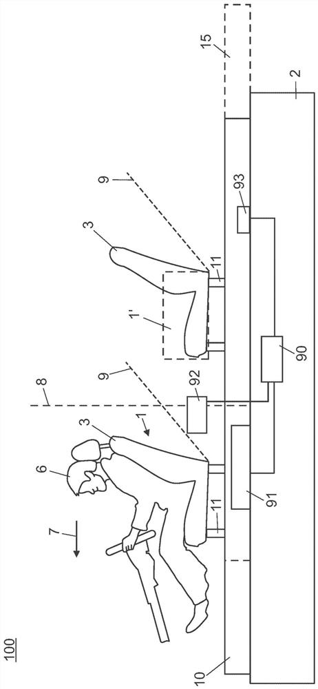
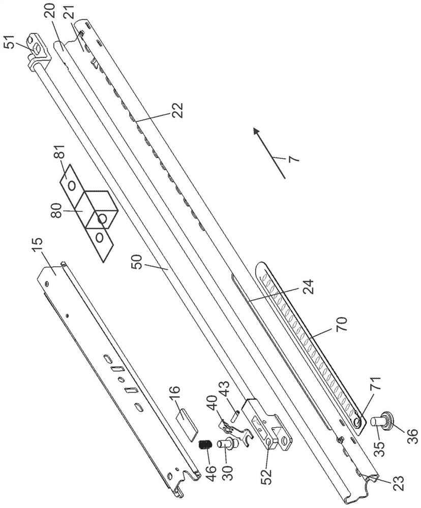
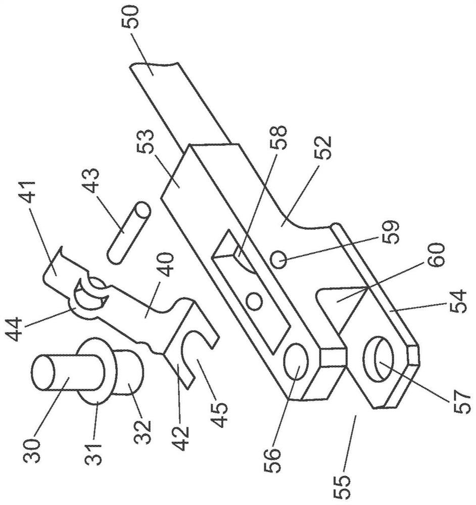
[0047] figure 1 The general structure of the seat rail module 100 according to the invention and its arrangement in the passenger compartment of a motor vehicle is shown in a schematic side view. The floor 2 of the vehicle is only schematically shown here and is suitably shaped according to the specifications of the vehicle manufacturer. exist figure 1 In and in the other figures, the direction of the main direction of travel is indicated by an arrow and reference numeral 7 . according to figure 1 , the seat rail module 100 comprises two rails 10 for longitudinal adjustment, which extend parallel to each other and are fastened to the floor 2 of the vehicle, each of the rails 10 for longitudinal adjustment Comprising a lower rail 20 (hereinafter also referred to as a lower rail) and an upper rail 15 (hereinafter also referred to as an upper rail), the lower rail 20 is connected to the floor 2 of the vehicle, and the upper rail 15 is supported such that the upper The guide r...


PUM


Abstract

A seat rail module for a vehicle seat is disclosed, with two longitudinal adjustment rails 10 arranged parallel to each other for guidance and longitudinal adjustment of the vehicle seat, said longitudinal adjustment rails each having a lower rail 20, which is fastenable in a positionally fixed manner to the floor 2 of a vehicle body, and an upper rail 15, which can be displaced longitudinally with respect to said lower rail, with a driving member 50 having a drive 91 coupled thereto for the longitudinal adjustment of the vehicle seat, with at least one deformation element 24 which is coupledto an associated longitudinal adjustment rail 10, and with at least one fastening element 30 for fastening the drive member 50 to the associated lower rail 20 or upper rail 15, wherein the vehicle seat 1 is fastenable to the upper rails 15, and the deformation element 24 is designed in order to be deformed when the vehicle seat is displaced in a main direction of travel 1, in order to dissipate energy in the event of a crash and to decelerate the vehicle seat. According to the invention, an actuator 40, 93 is provided for locking and unlocking the at least one fastening element, wherein, in alocked position of the fastening element 30 (figure 4a), the driving member 50 is secured directly to the associated lower rail 20 or upper rail 15 by the fastening element and, when the vehicle seat1 is adjusted beyond a predetermined limit setting 8, 9, the fastening element 30 is mechanically unlocked (figure 4b) such that the driving member 50 is coupled to the associated lower rail 20 or upper rail 15 via the deformation element 24. Unlocking of the at least one fastening element makes it possible for the force flow between the force introduced in the vehicle seat and the floor assemblyto be interrupted and for displacement of the upper rail relative to the lower rail over a certain distance to be permitted in order to dissipate impact energy. The distance can be predetermined herein a simple manner by the mechanical properties of the deformation element and the installation geometry thereof.

Description

technical field [0001] The present invention relates generally to a seat track module for a vehicle seat, in particular for a motor vehicle seat, and in particular to a seat track module having a Devices for decelerating vehicle seats in the event of a crash, especially in areas outside the effective range of conventional front occupant restraint systems, in particular front airbags. Background technique [0002] Vehicle design must take full account of occupant safety measures. In the case of vehicle seats located in the front area of ​​the vehicle, this is primarily done by front occupant restraint systems such as seat belt systems, seat belt tensioners and front airbags, which The system is designed to restrain the occupant in the relatively late stages of a crash and to provide additional protection, in particular, to the head and neck area. [0003] Additional protective measures are so-called seat-based restraints, which are coupled to the seat track modules and, in ...

Claims


Application Information

Patent Timeline
Patent Type & Authority Applications(China)
IPC IPC(8): B60N2/02B60N2/07B60N2/42B60N2/427
CPCB60N2/02B60N2/0705B60N2/4214B60N2/42709B60N2/42781B60N2/4279B60N2/02246
Inventor 谢尔盖·科斯汀
Owner BROSE FAHRZEUGTEILE GMBH & CO KG
Learn More