ISG type multifunctional electronic urgent safety clamp

An electronic device and emergency braking technology, applied in elevators, transportation and packaging, etc., to achieve the effect of improving operational safety

Active Publication Date: 2008-10-15
WITTUR
View PDF2 Cites 25 Cited by
  • Summary
  • Abstract
  • Description
  • Claims
  • Application Information

AI Technical Summary

Problems solved by technology

Therefore, additional recognition for other tasks such as precise position control is also quite problematic

Method used


Image

  • ISG type multifunctional electronic urgent safety clamp
  • ISG type multifunctional electronic urgent safety clamp
  • ISG type multifunctional electronic urgent safety clamp

Examples


Embodiment Construction

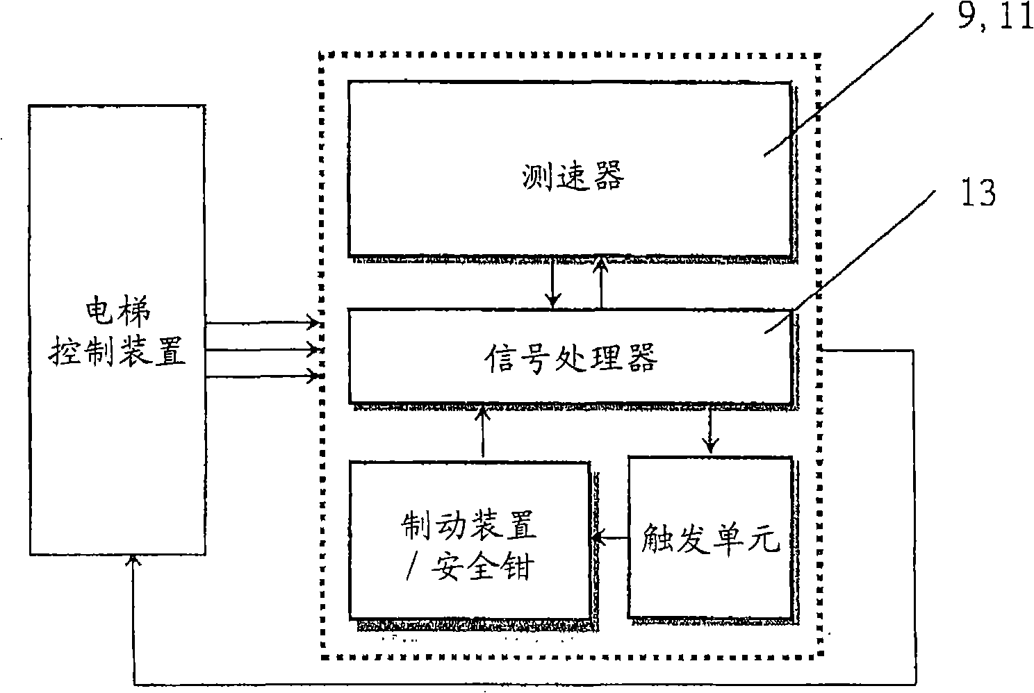
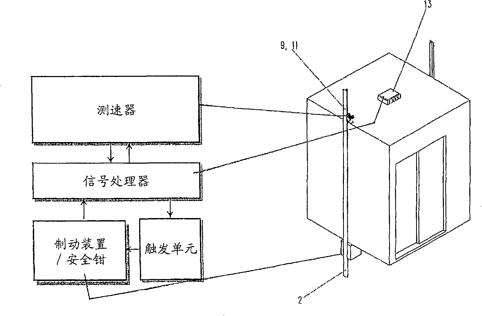
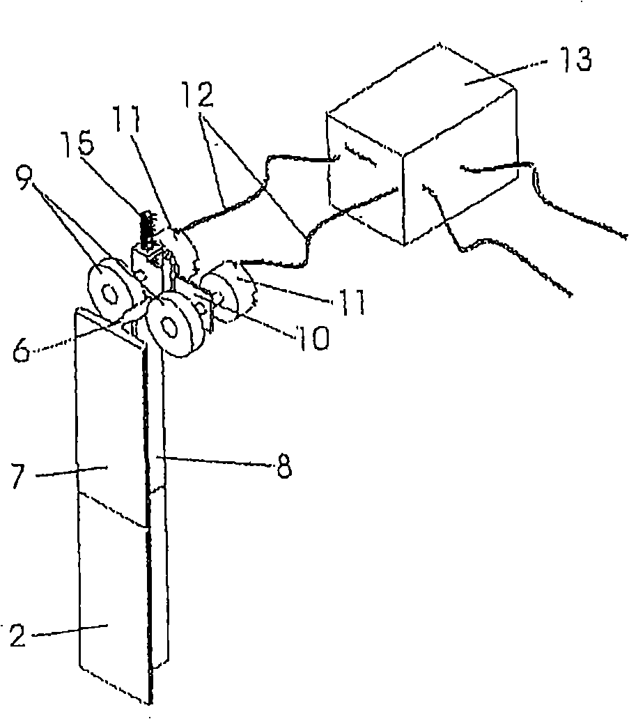
[0040] Figure 1 first shows the basic structure of the system. At least one unit, collectively referred to here as a speedometer, mounted on the car (that is to say moves with it), comprises two wheels 9 and a detector 11 here in the form of an encoder and associated support. An emergency braking electronic device 13 called "signal processor" is also fixedly installed on the car, and it sends an emergency braking signal in the event of overspeed or unacceptable acceleration or uncontrollable elevator operation. On the car is mounted the trigger unit that generates the force required to activate the brake or safety gear, and the brake or safety gear, also collectively referred to as the brake. The conventional elevator electronics, referred to as elevator control in FIG. 1, are installed in the hoistway (that is to say in the hoistway or in the associated drive machine room). The elevator control preferably has an emergency brake electronics 13 which receives the signal genera...


PUM


Abstract

The invention relates to an elevator comprising an elevator car that is guided inside an elevator shaft on guide rails. Said elevator also comprises electronics for inter alia travel control or regulation and an emergency braking device for preventing excess speed of the elevator car. Said emergency braking device has a braking device and a detector unit (11) the signal of which actuates the braking device when the elevator car reaches an excess speed. The detector unit (9, 11) comprises at least two wheels (8) that rest against a guide rail (2), each driving a respective detector (11) the signal of which is a measure for the rotational angle or rotational speed of the corresponding wheel. The electronics are adapted to functionally utilize the detector signal.; For this purpose, at least one detector signal is used during operation of the elevator within the admissible speed range for determining at least travel, speed and/or acceleration variable of the elevator car influencing the operation of the elevator system. The electronics actuate the braking device as soon as at least one of the detectors (11), by way of its detector signal, indicates an excess speed of the elevator car outside the admissible speed range.

Description

technical field [0001] The invention relates to an emergency braking device for an elevator car or cage (hereinafter generally referred to as elevator car) according to the preamble of claim 1 . Background technique [0002] Elevators equipped with brakes or safety gear or combined safety gear brakes, which occur at excessively high speeds (so-called overspeed), for example in the event of a malfunction of the controller, failure of the drive or brake, or breakage of the traction rope At high speeds, it is used to stop or brake the elevator car within the allowable limit value by means of the friction body acting on the guide rail. In this context, a braking device is generally understood to be a device which prevents the elevator car from overspeeding in the upward direction by stopping the elevator car or by stopping the counterweight at the end of the run as required by a buffer, As a result, abnormal operation of the elevator will be ended. In contrast to this, a devic...

Claims


Application Information

Patent Timeline
Patent Type & Authority Applications(China)
IPC IPC(8): B66B5/16
Inventor 沃尔夫冈·阿德丁格马库斯·埃尔恩德勒于尔根·卡纳
Owner WITTUR
Why Eureka
Try Eureka