Fault recording device state visual monitoring system and monitoring method

A fault recording device and monitoring system technology, applied in the fault location, measuring device, measuring electricity and other directions, can solve the problem of low visibility of recorded wave files, etc., to facilitate fault finding and analysis, improve state monitoring capabilities, safe and reliable The effect of technical support

Pending Publication Date: 2020-06-23
STATE GRID NINGXIA ELECTRIC POWER +3
View PDF0 Cites 3 Cited by
  • Summary
  • Abstract
  • Description
  • Claims
  • Application Information

AI Technical Summary

Problems solved by technology

[0005] In view of the above technical problems, the present invention provides a state visualization monitoring system and monitoring method of a fault wave recording device, which improves the fault monitoring capability of the VBE system equipment, solves the problem that the existing products have no online monitoring ability of optical power data, and the low degree of visualization of wave recording files Shortcomings

Method used


Image

  • Fault recording device state visual monitoring system and monitoring method
  • Fault recording device state visual monitoring system and monitoring method
  • Fault recording device state visual monitoring system and monitoring method

Examples


Embodiment 1

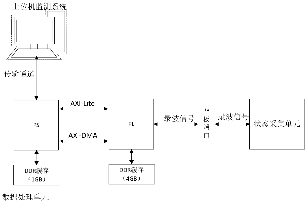
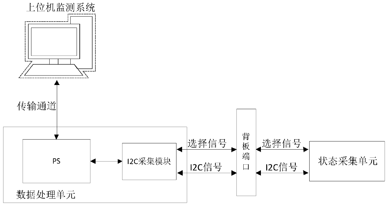
[0041] Such as figure 1 The state visualization monitoring system of a kind of fault recording device includes: a state acquisition unit, which is arranged on the interface board of the recording case, is used to collect the state data of the fault recording device in real time, and transfers the state data transmitted to the data processing unit;

[0042] The data processing unit is arranged on the core board of the recorder box, and is used to receive and store the data transmitted by the state acquisition unit, analyze and process the received data, and transmit the data to the host computer at the same time;

[0043] The upper computer is respectively connected to the state acquisition unit and the data processing unit by communication, and is used for displaying the data transmitted by the data processing unit.

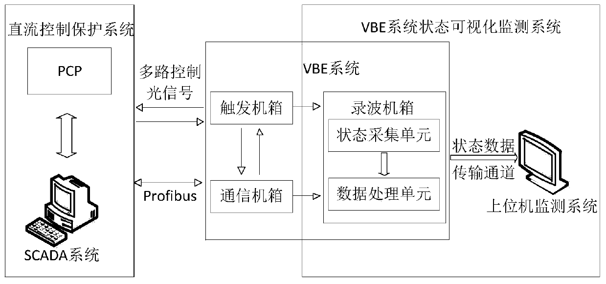
[0044] The VBE system includes a recorder box, a trigger box, and a communication box. The state acquisition unit is located on the interface board of the VBE s...

Embodiment 2

[0052] Based on the same inventive concept, the present invention also provides a method for visual monitoring of the state of a fault recording device, the method comprising:

[0053] The state acquisition unit arranged on the interface board of the recorder case collects the state data of the fault recorder in real time, and transmits the state data to the data processing unit;

[0054] The data processing unit arranged on the core board of the recorder box receives and stores the data transmitted by the state acquisition unit, analyzes and processes the received data, and transmits the data to the host computer at the same time;

[0055] The upper computer communicated with the state acquisition unit and the data processing unit respectively, displays the data transmitted by the data processing unit.

[0056] The data processing unit arranged on the core board of the recorder box receives and stores the data transmitted by the state acquisition unit, analyzes and processes ...


PUM


Abstract

The invention discloses a fault recording device state visual monitoring system and monitoring method, and the system comprises a state collection unit which is disposed on a recording case interfaceboard and is used for collecting the state data of a fault recording device in real time, and transmitting the state data to a data processing unit; a data processing unit arranged on the wave recording case core board and used for receiving and storing the data transmitted by the state acquisition unit, analyzing and processing the received data and transmitting the data to an upper computer; andan upper computer which is in communication connection with the state acquisition unit and the data processing unit and is used for displaying the data transmitted by the data processing unit. According to the fault recording device state visual monitoring system, the defects that an existing product has no optical power data on-line monitoring capacity and the visualization degree of a recordingfile is low are overcome by improving the equipment fault monitoring capacity of a VBE system.

Description

technical field [0001] The invention belongs to the technical field of high-voltage direct current transmission engineering, and in particular relates to a state visualization monitoring system and a monitoring method of a fault wave recording device. Background technique [0002] As one of the most important equipment in the converter station, the converter valve's operating status will directly affect the safety of the entire DC transmission system. With the increase of HVDC transmission projects, the failure of UHV converter valves has also increased, leading to an increase in the number of unplanned outages of DC projects, which has become the key to restricting the improvement of reliability indicators of UHVDC projects. Among them, the failure of the valve control system is the cause One of the main factors of converter valve failure is that its key components are affected by the environment during operation, and there is a certain probability of failure. For example, ...

Claims


Application Information

Patent Timeline
Patent Type & Authority Applications(China)
IPC IPC(8): G01R31/08
CPCG01R31/088
Inventor 史磊刘钊刘虹韦鹏张俊任佳丽柴斌刘若鹏李昊宁复茂谢伟锋
Owner STATE GRID NINGXIA ELECTRIC POWER
Why Eureka
Try Eureka