Self-tensioning energy-dissipating lock

A self-tensioning and locking technology, which is applied in the direction of transmission elements or pulley ropes or cables, excavation, sea area engineering, etc., can solve the problems that the wire rope is easy to deform, the length of the connection of the wire rope cannot be adjusted, and the performance of the overall protective device is affected. Achieve remarkable energy dissipation effect, easy to use and simple structure

Inactive Publication Date: 2017-01-04
德阳佰业机械设备有限公司 +1
View PDF0 Cites 4 Cited by
  • Summary
  • Abstract
  • Description
  • Claims
  • Application Information

AI Technical Summary

Problems solved by technology

[0002] With the rapid development of my country's economic construction, high-speed railways, highways, water conservancy and hydropower and other infrastructures are vigorously implemented, and a large number of projects are built on the mountain or near the mountain, and more and more projects need to be protected from falling rocks; existing Most of the docking components of steel structure protection products use end locks that cannot adjust the variable of the wire rope; the wire rope is easily deformed by the influence of climate and temperature in different seasons, thus affecting the performance of the overall protection device; moreover, ordinary end locks lock the wire rope After that, the length of the wire rope connection cannot be adjusted; at the same time, ordinary end locks do not have the function of energy dissipation, and it is difficult to meet the docking needs of current multi-protection products

Method used


Image

  • Self-tensioning energy-dissipating lock
  • Self-tensioning energy-dissipating lock
  • Self-tensioning energy-dissipating lock

Examples


Embodiment Construction

[0027] The present invention will be further described below in conjunction with the accompanying drawings and specific embodiments.

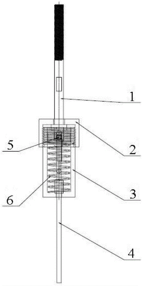
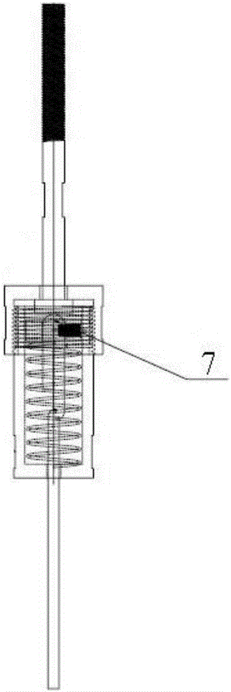
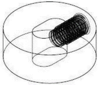
[0028] Such as Figure 1-3 As shown, a self-tensioning energy-dissipating lockset includes an upper lockset 2 and a lower lockset 3 arranged below it; the lower part of the upper lockset 2 is provided with an internal thread, and the upper part of the lower lockset 3 is provided with an external thread that matches the internal thread; The upper part of the upper lock 2 is connected with a screw 1; the lower lock 3 is a cylindrical structure, the upper part of which is a hollow structure, and the lower part is provided with a central hole for the wire rope 4 to pass through; The spring 6; the spring 6 is provided with a locking iron ring 7; the center of the locking iron ring 7 is provided with a bar-shaped hole for the steel wire rope 4 to pass through; Fasten the bolts.

[0029] When in use, the upper lock 2 and the lower lock 3 are separat...


PUM


Abstract

The invention discloses a self-tensioning energy-dissipating lock which comprises an upper lock body and a lower lock body arranged under the upper lock body; an internal thread is formed in the lower part of the upper lock body; an external thread matched with the internal thread is formed on the upper part of the lower lock body; a screw is connected to the upper part of the upper lock body; the lower lock body adopts a cylindrical structure; the upper part of the lower lock body adopts a hollow structure; a central hole, through which a wire rope can penetrate, is formed in the lower part of the lower lock body; a spring, of which the size is matched with the inner diameter of the lower lock body, is arranged in the hollow structure; a locking iron hoop is arranged above the spring; a strip-shaped hole, through which the wire rope can penetrate, is formed in the center of the locking iron hoop; a fastening bolt used for fastening the wire rope is arranged on one side of the locking iron hoop. The self-tensioning energy-dissipating lock can eliminate impact energy and balance deformation when temperature and climate change, is simple in structure, convenient to use, and remarkable in energy-saving effect, and can be used repeatedly, thereby having very strong practicality.

Description

technical field [0001] The invention relates to a docking lock, in particular to a self-tensioning energy-dissipating lock. Background technique [0002] With the rapid development of my country's economic construction, high-speed railways, highways, water conservancy and hydropower and other infrastructures are vigorously implemented, and a large number of projects are built on the mountain or near the mountain, and more and more projects need to be protected from falling rocks; existing Most of the docking components of steel structure protection products use end locks that cannot adjust the variable of the wire rope; the wire rope is easily deformed by the influence of climate and temperature in different seasons, thus affecting the performance of the overall protection device; moreover, ordinary end locks lock the wire rope Finally, the length of the wire rope connection cannot be adjusted; at the same time, ordinary end locks do not have the function of energy dissipation...

Claims


Application Information

Patent Timeline
Patent Type & Authority Applications(China)
IPC IPC(8): F16G11/00F16F15/04
CPCE02B3/124E02D17/202F16F15/04F16G11/00
Inventor 吕汉川邓建义陈效星洪习成张一帆田波
Owner 德阳佰业机械设备有限公司
Why Eureka
Try Eureka