Electrostatic actuator

a technology of actuators and actuators, applied in the direction of generators/motors, mechanical equipment, instruments, etc., can solve the problems of inability to obtain a sufficient the amount of displacement of the movable element can be increased, and the operation of the actuator becomes unstable, so as to achieve the effect of greatly improving the reliability

Inactive Publication Date: 2005-08-18
MURATA MFG CO LTD
View PDF6 Cites 17 Cited by
  • Summary
  • Abstract
  • Description
  • Claims
  • Application Information

AI Technical Summary

Benefits of technology

[0012] To overcome the problems described above, preferred embodiments of the present invention provide an electrostatic actuator in which the movable element is largely and stably displaced, transverse locational deviations of the movable element are prevented, a sufficient amount of displacement of the movable element is obtained, and the reliability is greatly improved.
[0021] As a result, when the movable element is displaced by a large amount, even if an asymmetrical electrostatic force is increased in the transverse direction (X-axis direction), the rigidity in the transverse direction of the support beams is increased, and thus, while the support beams are bent in the displacement direction of the movable element, locational deviations in the transverse direction of the movable element are minimized because of the high rigidity. Therefore, even if the amount of displacement of the moving element is set to be large, the movable element is stably and reliably displaced between the initial position and the switching position and, the amount of displacement of the movable element is sufficiently secured while the reliability of the actuator is greatly improved.
[0022] Furthermore, in at least one preferred embodiment of the present invention, each of the arm portions of the support beam includes a plurality of bar-shaped elements and the bar-shaped elements are connected to the connection portion at different locations in the Y-axis direction. In this way, the connection portion is connected to the arm portions at a plurality of locations and the rigidity at these connecting points is increased. Accordingly, when the support beams are bent and deformed, displacement such that the connection portion undulates in the X-axis direction at the end portion of the arm portions is minimized and the rigidity in the X-axis direction of the support beams as a whole is increased.
[0023] Furthermore, in at least one preferred embodiment of the present invention, the width dimension of the connection portion is set to be greater than the width dimension of the arm portions, the rigidity of the connection portion is increased, and the elasticity (spring action) is minimized. Thus, when the support beams are bent and deformed, the bending and deformation in the X-axis direction of the connection portion is minimized, and, as a result, the spring constant in the X-axis direction of the support beams is increased.
[0024] Furthermore, in at least one preferred embodiment of the present invention, since the width dimension of the connection portion is greater than the width dimension of each bar-shaped element of the arm portions, the bending and deformation in the X-axis direction of the connection portion is minimized by increasing the rigidity of the connection portion, and the spring constant in the X-axis direction of the support beams is increased.
[0026] Moreover, in at least one preferred embodiment of the present invention, while the size of each electrode is reduced by using comb-shaped fixed and movable electrodes, a sufficient opposing area is maintained between the electrodes, and the movable element is efficiently driven by a large electrostatic force. Since transverse locational deviations of the movable element are prevented, a short-circuit between the facing electrodes having a very small gap therebetween is prevented.

Problems solved by technology

However, when the amount of displacement of the movable element is increased, locational deviations in the transverse direction (X-axis direction) perpendicular to the direction of displacement of the movable element are likely to occur and the operation of the actuator becomes unstable.
Therefore, in the prior art, the amount by which the displacement of the movable element can be increased is limited, and it is difficult to obtain a sufficient amount of displacement of the movable element while maintaining the reliability of the actuator.
As a result, when the amount of displacement of the movable element is set to be large, the actuator may not operate properly.

Method used


Image

  • Electrostatic actuator
  • Electrostatic actuator
  • Electrostatic actuator

Examples


Embodiment Construction

[0040] Hereinafter, the electrostatic actuators according to preferred embodiments of the present invention will be described in detail with reference to the drawings.

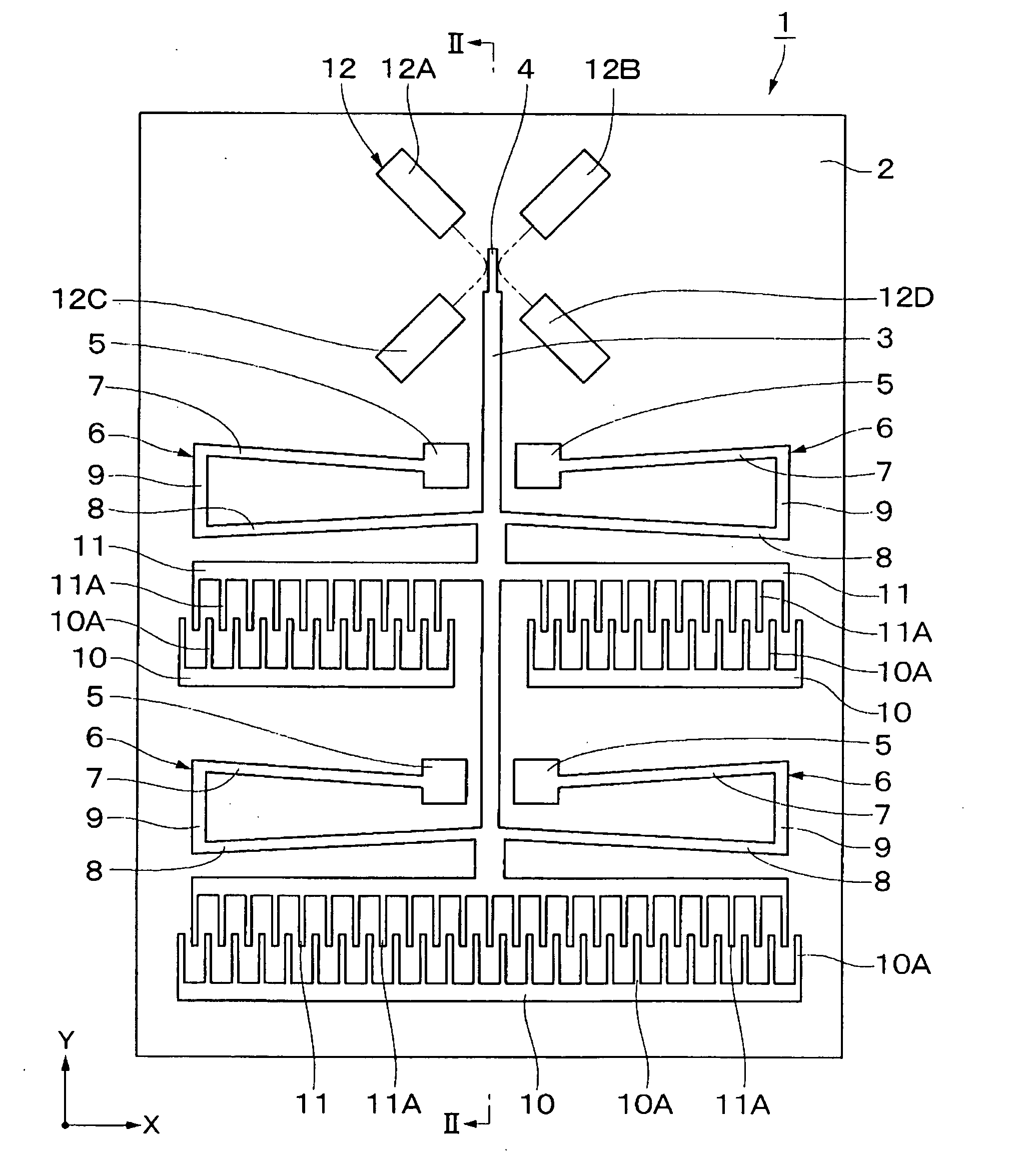
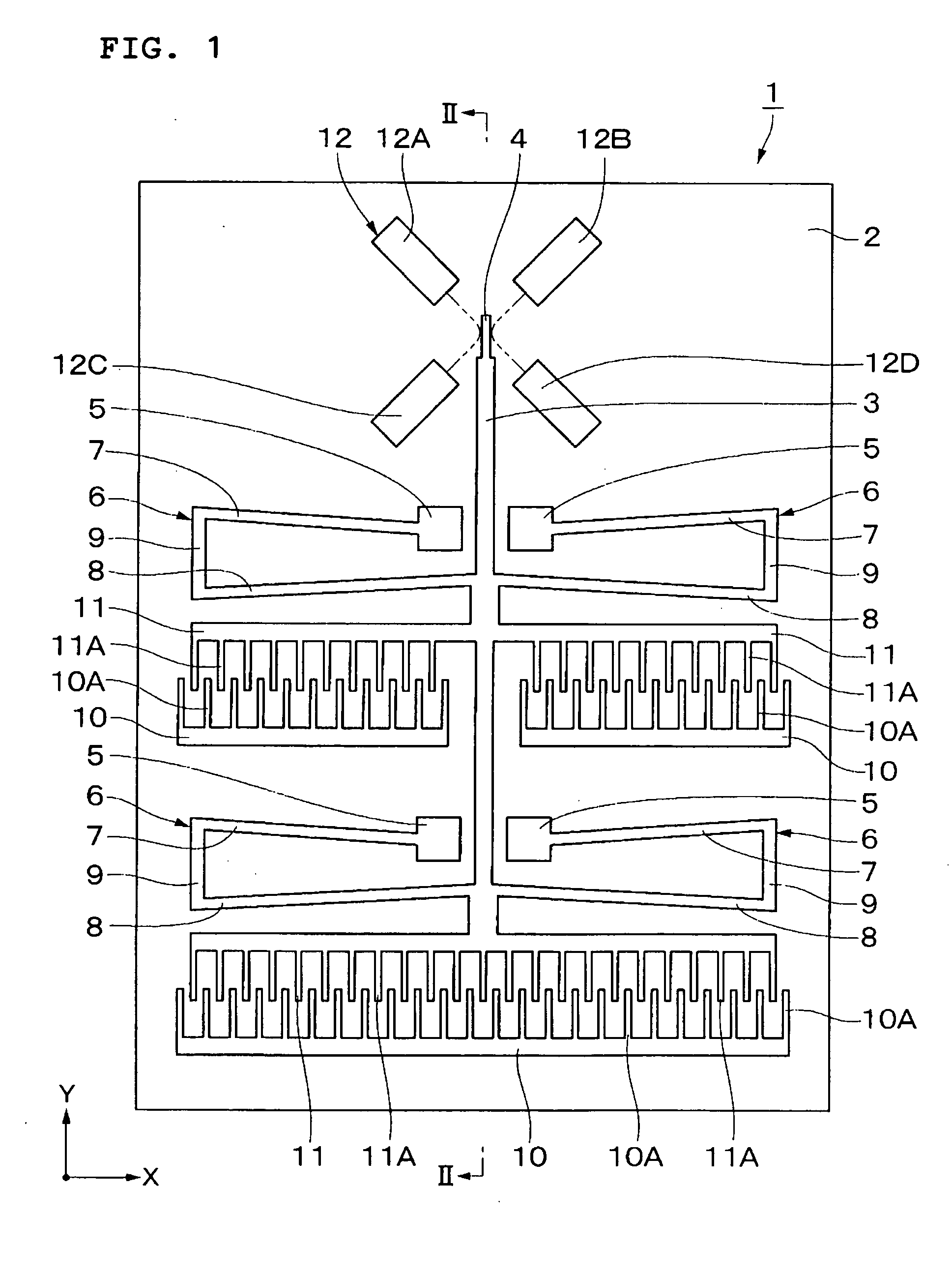
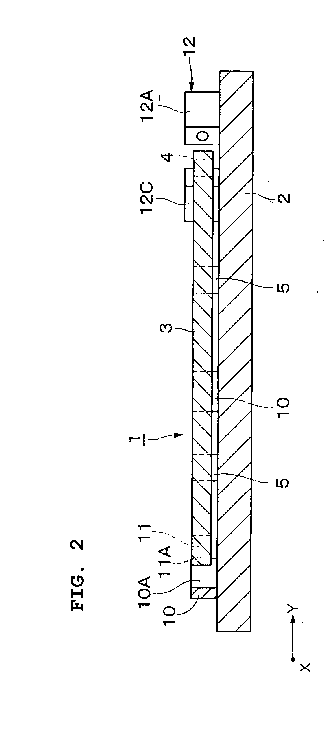
[0041] FIGS. 1 to 6 show an electrostatic actuator according to a first preferred embodiment of the present invention and, in the present preferred embodiment, a case in which the electrostatic actuator is used in an optical switching device is described as an example.

[0042] In the drawings, reference numeral 1 represents an optical switching device and reference numeral 2 represents a substrate defining the base of the optical switching device 1. The substrate 2 is made of, for example, a glass plate having a size of a few mm square and horizontally extended along X and Y axes perpendicular to each other.

[0043] On the top surface of the substrate 2, a movable element 3, a mirror portion 4, support beam fixing portions 5, support beams 6, fixed electrodes 10, movable electrodes 11, and other elements to be described...


PUM


Abstract

An electrostatic actuator includes a substrate upon which substantially U-shaped support beams are arranged such that a movable element is displaceable in the Y-axis direction. Then, the movable element is displaced from an initial position to a switching position by an electrostatic force between electrodes. When the movable element is at the initial position, the support beams are configured such that the arm portions of the support beams are not parallel to each other and, when the movable element is displaced by a large amount to the vicinity of the switching position, the arm portions are extended in the X-axis direction so as to be substantially parallel to each other. Thus, since the spring constant in the X-axis direction of the support beams is increased, transverse locational deviations when the movable element is displaced and short-circuiting by the deviations are prevented and, as a result, the movable element can be stably displaced by a large amount.

Description

BACKGROUND OF THE INVENTION [0001] 1. Field of the Invention [0002] The present invention relates to an electrostatic actuator suitably used to drive a movable element disposed on a substrate by an electrostatic force between electrodes. [0003] 2. Description of the Related Art [0004] An electrostatic actuator is generally used in optical communication components, such as optical switches, optical shutters, optical attenuators, angular velocity sensors, resonators, and other suitable devices (see, for example, U.S. Pat. No. 6,229,640). [0005] A conventional electrostatic actuator is formed by subjecting a low-resistance silicone to an etching process. The electrostatic actuator includes a substrate, a bar-shaped movable element disposed on the substrate with a space therebetween, a plurality of support beams provided between the substrate and the movable element such that the support beams may be bent and deformed, and a drive portion for driving the movable element by an electrosta...

Claims


Application Information

Patent Timeline
Patent Type & Authority Applications(United States)
IPC IPC(8): H02N1/00G02B26/08
CPCH02N1/008E02F3/966F15B21/008
Inventor TAMURA, MASAYA
Owner MURATA MFG CO LTD
Why Eureka
Try Eureka