Endoscope

a technology of endoscope and endoscope, which is applied in the field of endoscope, can solve the problems of fatigue inability to maintain the flexibility of the insertion portion, and inability to give play to the length of the wire, so as to prevent the meandering of the operating wire, prevent any damage to the wire, and simple structure

Inactive Publication Date: 2012-11-13
FUJIFILM CORP
View PDF15 Cites 6 Cited by
  • Summary
  • Abstract
  • Description
  • Claims
  • Application Information

AI Technical Summary

Benefits of technology

[0010]The invention is made in consideration of the above situations, and an object of the invention is to provide an endoscope capable of preventing meandering of a bending operating wire by simple structure, and thereby, preventing any damage of the wire.

Problems solved by technology

If such meandering is repeated frequently, there is a probability that the wires may be damaged by fatigue.
However, when regions where the wires become naked are eliminated, play may not be given to wire length, and the flexibility of the insertion portion 19 may not be maintained.
Therefore, the structure becomes complicated.

Method used


Image

  • Endoscope
  • Endoscope
  • Endoscope

Examples


first embodiment

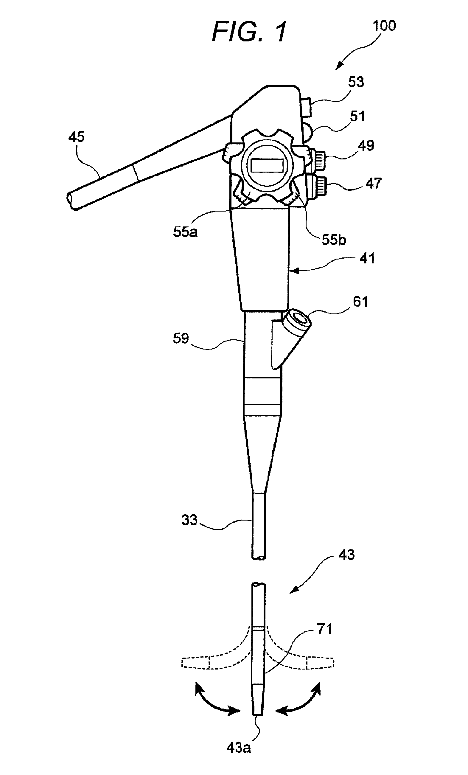
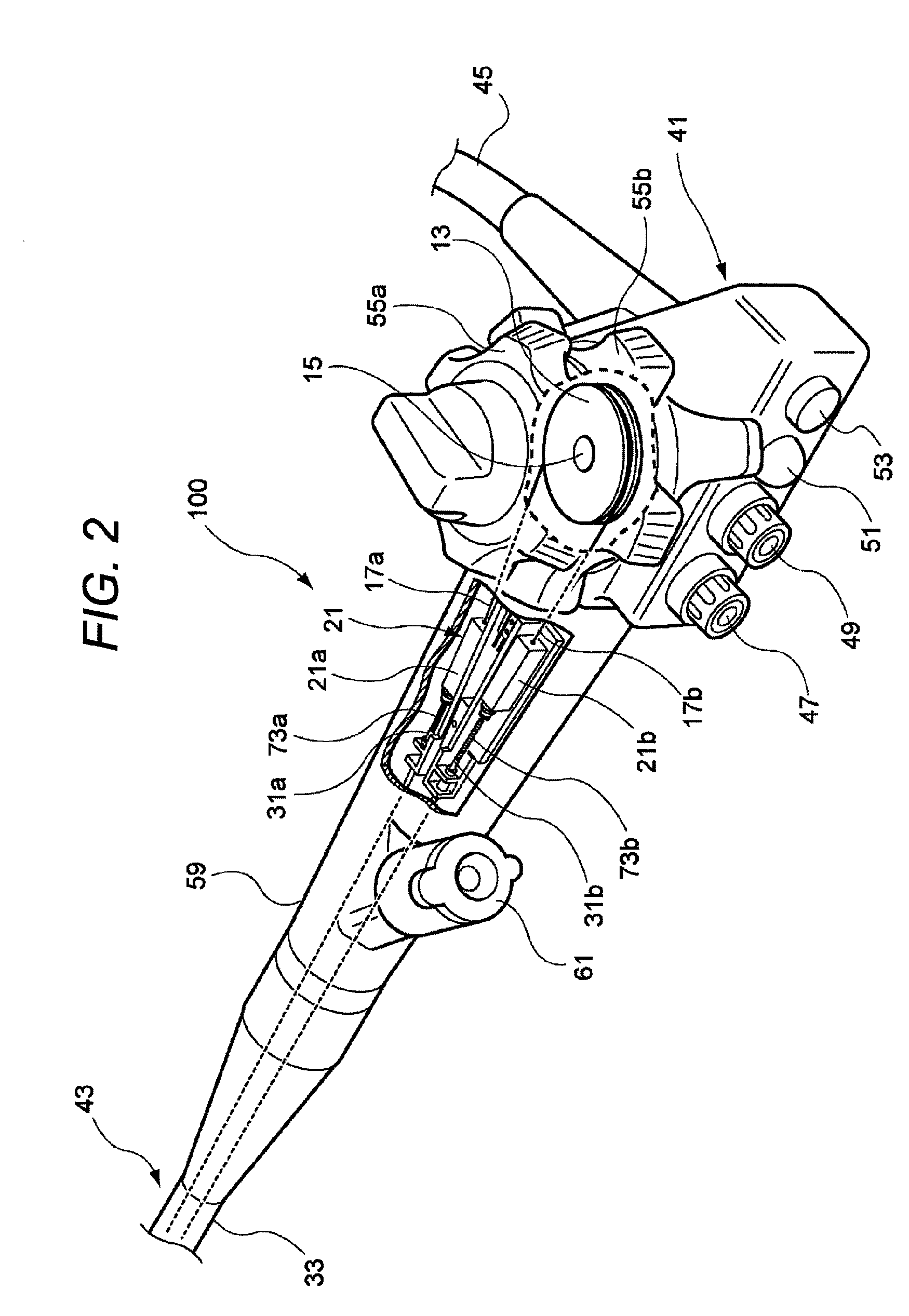
[0042]FIG. 1 is an entire configuration diagram of an endoscope according to the invention, and FIG. 2 is a partially cutaway perspective view of an operating portion shown in FIG. 1. In addition, description will be made with the same reference numerals being given to the same members as the members shown in FIG. 12.

[0043]An endoscope 100 includes an operating portion 41, and an insertion portion 43 connected to the operating portion 41 and inserted into an abdominal cavity. A universal cable 45 is connected to the operating portion 41, and a light guide connector (not shown) is provided at the tip of the universal cable 45. The light guide connector is detachably connected to a light source, and illumination light is sent to an illumination optical system at a tip 43a of the insertion portion. Additionally, an electrical connector is connected to the light guide connector, and this electrical connector is detachably connected to a processor.

[0044]An air supply / water supply button ...

second embodiment

[0058]Next, the endoscope according to the invention will be described.

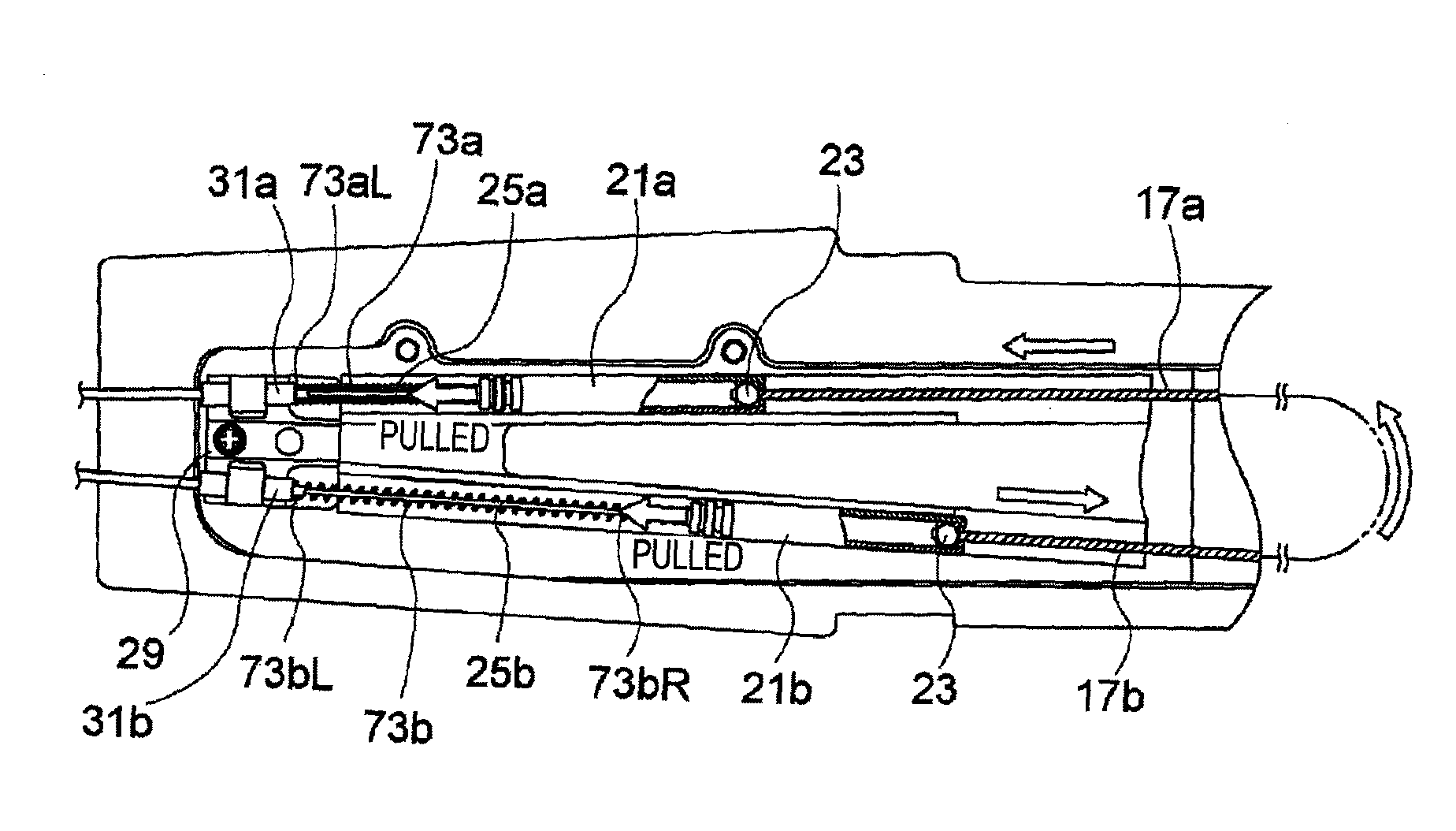
[0059]FIG. 6 is an enlarged plan view of the inside of an operating portion according to the second embodiment to which coil springs are fixed, and FIG. 7 is an explanatory view of the operation of the second embodiment. In addition, in the following respective embodiments, the same reference numerals will be given to the same members as the members shown in FIGS. 1 to 5, and duplicate description will be omitted. In this endoscope, one ends (left ends) 73aL and 73bL of the coil springs 73a and 73b are fixed to the wire-receiving members 31a and 31b, respectively, and the other ends (right ends) 73aR and 73bR thereof are fixed to the sleeves 21a and 21b, respectively.

[0060]According to this endoscope, both ends of the coil springs 73a and 73b are fixed to the wire-receiving members 31a and 31b and the sleeves 21a and 21b. Thereby, even if the distance between the wire-receiving members 31a and 31b and the sleeves...

third embodiment

[0062]Next, the endoscope according to the invention will be described.

[0063]FIG. 8 is an enlarged plan view the inside of an operating portion according to the third embodiment in which compression spring members are provided inside sleeves, respectively, FIG. 9 is an explanatory view of the operation of the third embodiment, and FIG. 10 is an explanatory view showing the operation of a compression spring member.

[0064]In this endoscope, as shown in FIG. 8, compression spring members 75a and 75b which biases the slip-off preventing members 23 toward the operating wires 17a and 17b are provided inside the sleeves 21a and 21b, respectively. The compression spring members 75a and 75b may be coil springs which are housed in a compressed state. A left end of each spring member abuts on the engaging tube 65, and the other end thereof abuts on the slip-off preventing member 23. The compression spring members 75a and 75b may be proper spring members, such as leaf springs, besides the coil s...


PUM


Abstract

An endoscope includes an insertion portion which has a bending portion, a wire which is fixed to an end of a distal side of the bending portion and is pushed along the insertion portion, an operating portion which is provided on a proximal side of the insertion portion opposite to the bending portion, and a wire-connecting member which is interposed in the wire between the insertion portion and the operating portion to form an allowance in a in which the wire is pushed and pulled, wherein a portion of the wire between the wire-receiving member and the wire-connecting member is inserted into the coil spring so that the coil covers a surface of the portion of the wire.

Description

[0001]The present invention claims priority from Japanese Patent Application No. 2008-011323 filed on Jan. 22, 2008, the entire content of which is incorporated herein by reference.BACKGROUND OF INVENTION[0002]1. Field of the Invention[0003]The present invention relates to an endoscope having a bending portion capable of being bent by wires, and particularly, to an improved technique of preventing meandering of the wires.[0004]2. Description of the Related Art[0005]An endoscope is composed roughly of an insertion portion inserted into an abdominal cavity or the like, and an operating portion to which a proximal end of this insertion portion is connected. In the insertion portion, a distal end including an image pick-up unit or the like, a bending portion which may be bent, and a long flexible portion which constitutes the proximal end of the insertion portion and is connected to the operation portion are sequentially connected toward the operating portion from the distal side. An op...

Claims


Application Information

Patent Timeline
Patent Type & Authority Patents(United States)
IPC IPC(8): A61B1/00
CPCA61B1/0052G02B23/2476A61B1/0057
Inventor TORII, YUICHI
Owner FUJIFILM CORP
Why Eureka
Try Eureka