Multi-access blanket

a blanket and multi-access technology, applied in the field of convective heating blankets, can solve the problems of cumbersome use of multiple blankets, and achieve the effect of facilitating the flow of heated air

Active Publication Date: 2012-11-13
SMITHS MEDICAL ASD INC
View PDF8 Cites 5 Cited by
  • Summary
  • Abstract
  • Description
  • Claims
  • Application Information

AI Technical Summary

Benefits of technology

[0003]The convective blanket of the present invention is a full body inflatable warming blanket that has a main body having a central section that extends from a proximal portion of the blanket to the foot or distal end of the blanket. The proximal portion of the blanket has a proximal end that is below the head of the patient. A head portion is connected to and in fluid communication with the proximal portion. Extending orthogonally to either side of the central section are a plurality of peripheral sections each foldable relative to the central section for selectively exposing a body part or portion of the patient along the length of the blanket. Adjacent peripheral sections are connected by a frangible or tearable common seal that allows the peripheral sections to be separated and movable relative to the rest of the blanket, for example by being folded toward the central section of the blanket to selectively expose the body part of the patient covered by that particular peripheral section. The frangible or tearable common seal that separates adjacent peripheral sections may already be cut along its length or may have a series of slits along its length that allows the adjacent peripheral sections to readily separate from each other when a tearing force is applied to the common seal.
[0006]To facilitate the flow of heated air within the blanket, there is provided at the central section of the blanket a central seal that extends from the proximal portion of the blanket though the middle portion to approximately the beginning of the distal portion of the blanket. A second central seal in longitudinal alignment with the first central seal extends along the distal portion of the blanket so that two through channels are provided along the central section of the blanket for guiding the heated air from the proximal portion of the blanket to the distal portion of the blanket.

Problems solved by technology

However, the use of multiple blankets often is cumbersome.

Method used


Image

  • Multi-access blanket
  • Multi-access blanket
  • Multi-access blanket

Examples


Embodiment Construction

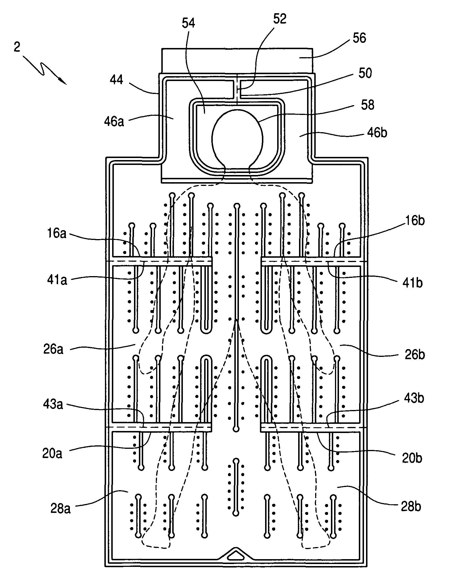
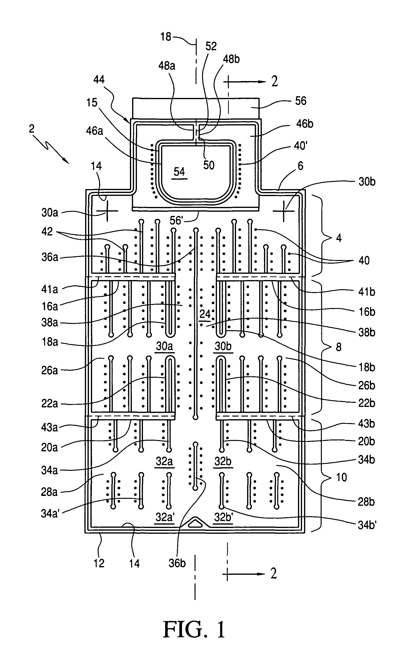
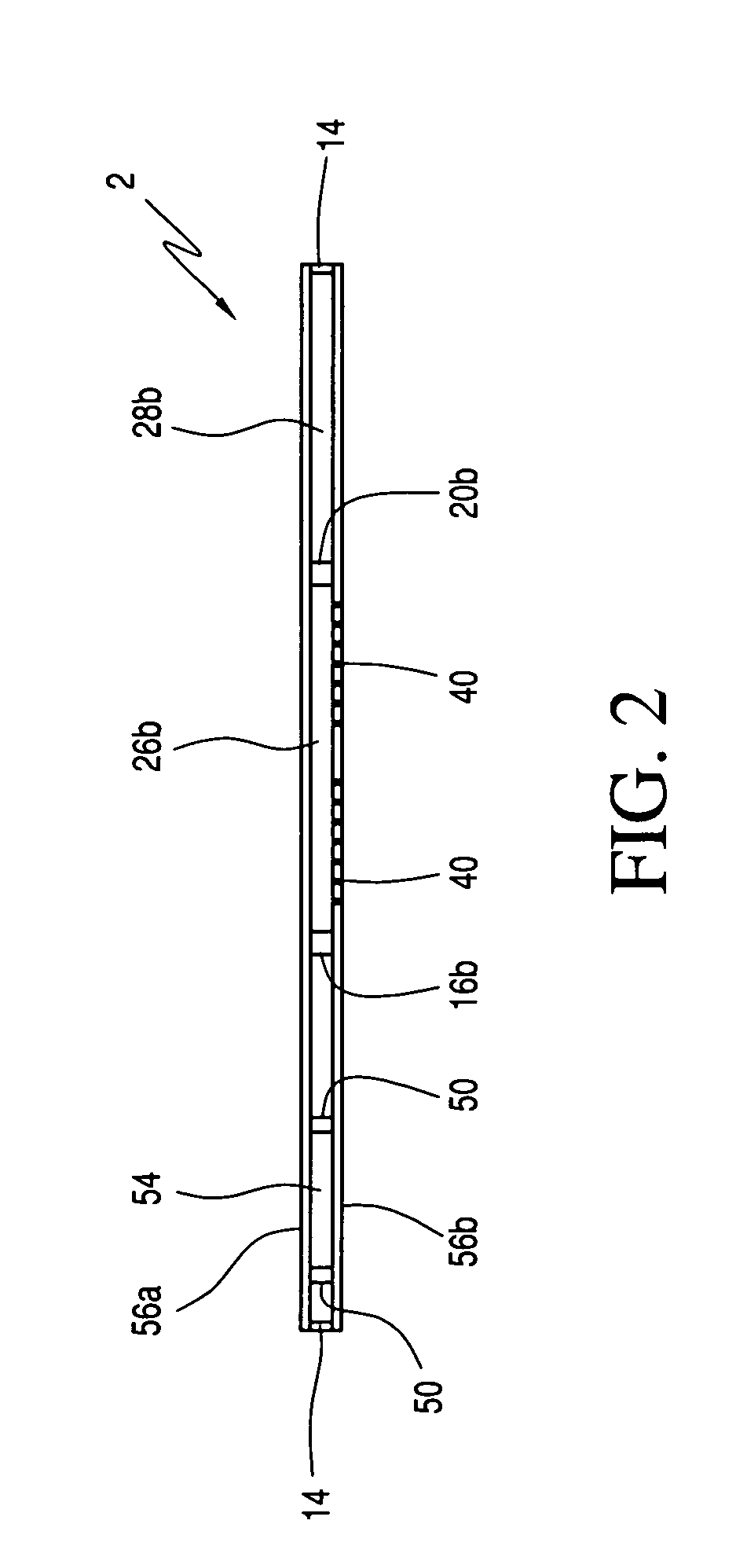
[0015]With reference to FIG. 1, blanket 2 of the instant invention is shown to have a proximal portion 4 that extends from a proximal end 6 to the beginning of a middle portion 8, which in turn extends to the beginning of a distal portion 10 that ends at a distal end 12 of the blanket. Proximal portion 4, middle portion 8 and distal portion 10 in combination may be referred to as the main body of blanket 2. Blanket 2 is made of two air impermeable sheets or layers as is conventionally known. In FIG. 1, for illustration purposes, the sheets are shown together with the upper sheet superposed over the lower sheet so that the lower sheet, or the bottom layer of the blanket with the myriad apertures, can also be seen. The two sheets are sealingly bonded at various locations of the blanket to form an inflatable structure as is also conventionally known. For example, the periphery of the blanket is bonded by an outer periphery seal 12 and an inner periphery seal 14. The enclosure formed by...


PUM


Abstract

A convective warming blanket has a head portion and a plurality of peripheral sections extending orthogonally from each side of a central section that extends uninterrupted from a proximal end below the head portion to a distal foot end of the blanket. Each peripheral section is separable from its adjacent peripheral section by a frangible or tearable common seal. At least one through passage connects each peripheral section to the central section, so that the peripheral sections are inflated when heated air is input to the blanket. The multiple peripheral sections each are movable relative to the central section, so that different body parts of the patient may be selectively accessed. The head portion of the blanket is formed by two tubular sections that extend from the proximal portion of the blanket to encircle the head of the patient, when the blanket is placed over the patient.

Description

FIELD OF THE INVENTION[0001]The present invention relates to convective warming blankets, and more particularly relates to a blanket that is designed to allow a clinician or surgeon to selectively gain access to different areas of the body of the patient covered by the blanket.BACKGROUND OF THE INVENTION[0002]The use of inflatable convective blankets for pre-operative, post-operative and / or intra-operative warming of a patient in surgery or to prevent the patient from hypothermia is known. During surgery, there is often a need for the surgeon or clinician to gain access to a given part of the body of the patient. Previously, multiple warming blankets may be used to ensure that a given body part of the patient is exposed, while other body parts of the patient are covered to maintain warmth to the patient. However, the use of multiple blankets often is cumbersome. Moreover, there are instances where after a given body part of the patient has been accessed, other body parts of the pati...

Claims


Application Information

Patent Timeline
Patent Type & Authority Patents(United States)
IPC IPC(8): A61F7/00
CPCA61F7/0097A61F2007/0288A61F2007/0271A61F2007/006
Inventor PIERRE, JOSEPHSTARR, RACHELSTEC, ALAN
Owner SMITHS MEDICAL ASD INC
Why Eureka
Try Eureka