Flow-through pressure sensor apparatus

a flow-through pressure sensor and flow-through technology, which is applied in the direction of fluid pressure measurement by mechanical elements, instruments, measurement devices, etc., can solve the problems of limiting the frequency response of the device, the dead volume may interfere with the smooth, laminar flow of fluid, and the pressure connection configuration available on most pressure sensors is ‘dead-ended’. , to achieve the effect of reducing the dead space of the flow tube, minimizing the chance of dust or similar contaminants becoming trapped in the apparatus

Active Publication Date: 2012-11-20
HONEYWELL INT INC
View PDF24 Cites 5 Cited by
  • Summary
  • Abstract
  • Description
  • Claims
  • Application Information

AI Technical Summary

Benefits of technology

[0010]The aforementioned aspects and other objectives and advantages can now be achieved as described herein. A flow-through pressure sensor apparatus that reduces the dead space of a flow tube utilized to provide fluid communication between a pressure sense die and a fluid with an absolute minimum trapped volume is disclosed. A cover (e.g., plastic) with two-molded ports can be added to one side of the pressure sense die utilizing molded-in solder pins to improve ruggedness and rigidity. The pressure sense die can be mounted to or located within a housing, depending upon design considerations. A temperature and a humidity sensor can also be mounted to a substrate (e.g., ceramic) in the flow path and can be connected to a programmable compensation integrated circuit on the opposite side utilizing a clip end of mounting pins or by vias through the substrate outside a pressurized area.
[0011]The pressure sense die can be mounted either on top or bottom of the substrate to minimize the chances of dust or similar contaminants becoming trapped in the apparatus. The covers can be molded so as to minimize disruption to the flow path and without hard edges that can trap contaminants. The sense die can be mounted with or without a glass constraint layer to minimize internal dead volumes. The temperature can be measured utilizing the sense die, an internal temperature sensor in the ASIC, or an external temperature sensor mounted directly in the flow path.
[0012]Such an apparatus can be easily adaptable to flow tubes of different sizes and can be connected with different connections, or with a molded-in connector. The sensor housing can be implemented as a single-in-package (SIP), dual-in-package (DIP), or a surface mount type (SMT), which is low cost and smaller in size. The sense die and the programmable compensation integrated circuit can be electrically connected together internally or externally of the package. Also, the flow tubes with 180 or 90-degree turns can also be easily embodied. Such an apparatus reduced the dead space and smaller in size hence the apparatus can be easily fit into a constricted operating environment and can be attached to a wide variety of sizes and shapes of flow tubes and containers.

Problems solved by technology

Such pressure connection configurations available on most pressure sensors are ‘dead-ended’.
Dead spaces affect the cleanliness of the device because any dead spaces in the conduit can trap a portion of the fluid and collect contaminants.
When measuring the pressure of the fluid flowing in the conduit, dead volumes may also interfere with the smooth, laminar flow of the fluid.
In high-speed dynamic applications, such tubing and fittings can limit the frequency response of the device.
Furthermore, in order to maintain extreme purity of the fluids, it has heretofore been necessary to dismantle the conduit and / or transducer manually and then clean all of the regions accessible to the fluids, which is costly and time consuming.
Also, such connecting plumbing makes the measurement of a temperature of the media, or the humidity, or other characteristic of the media difficult or impossible.

Method used


Image

  • Flow-through pressure sensor apparatus
  • Flow-through pressure sensor apparatus
  • Flow-through pressure sensor apparatus

Examples


Embodiment Construction

[0023]The particular values and configurations discussed in these non-limiting examples can be varied and are cited merely to illustrate at least one embodiment and are not intended to limit the scope thereof.

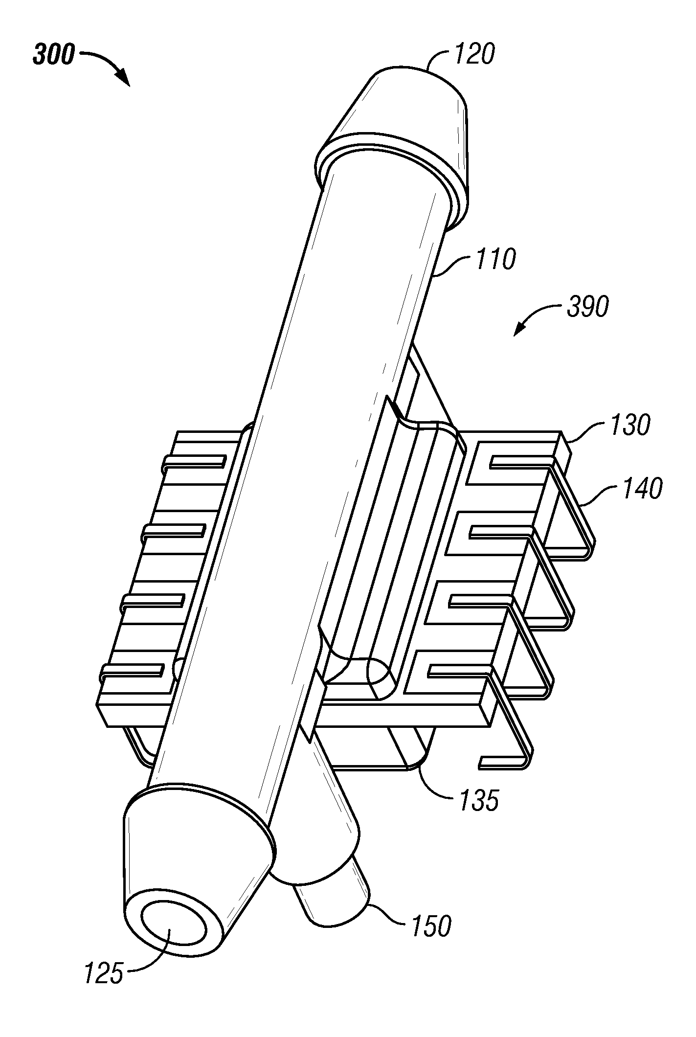
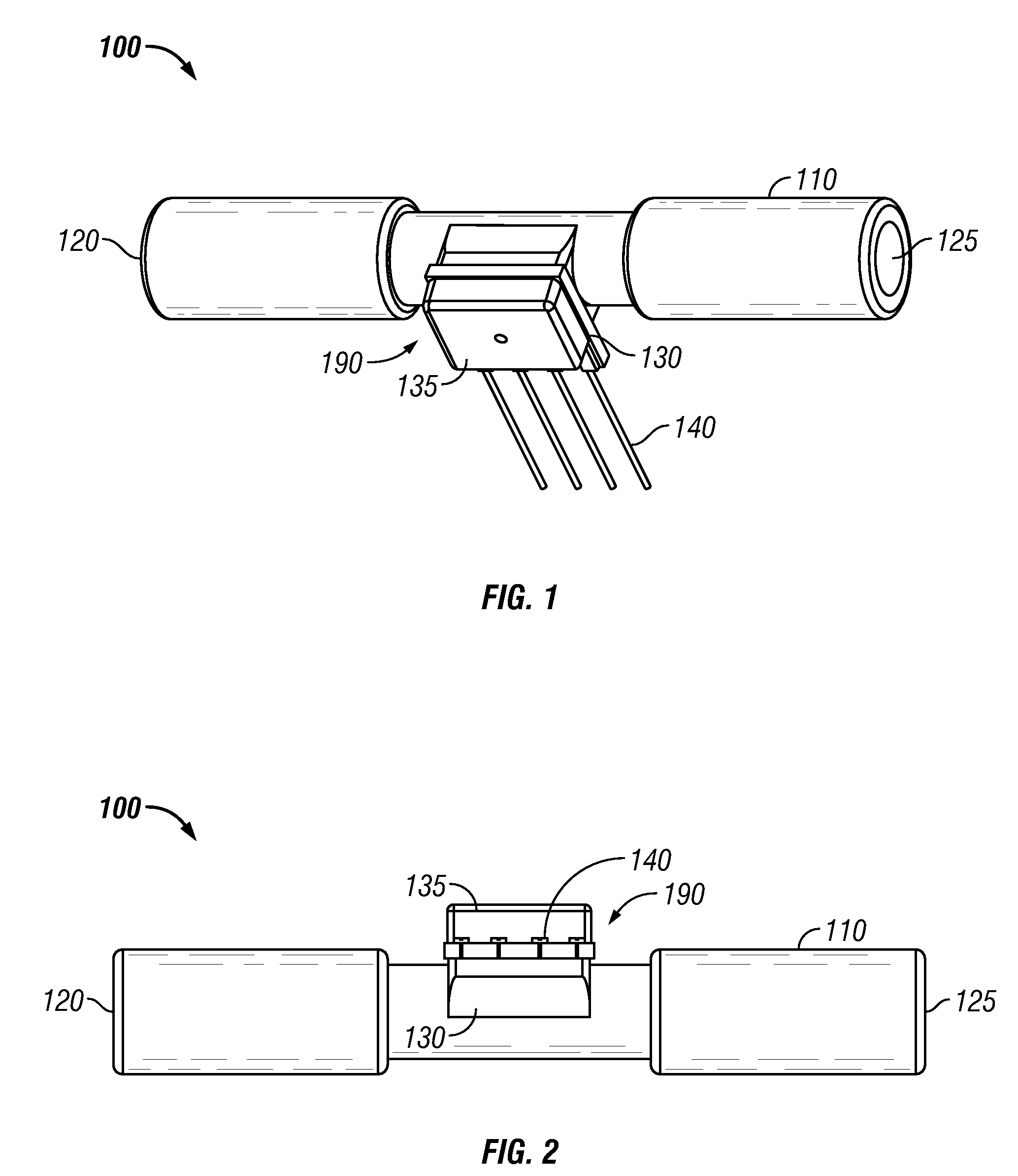
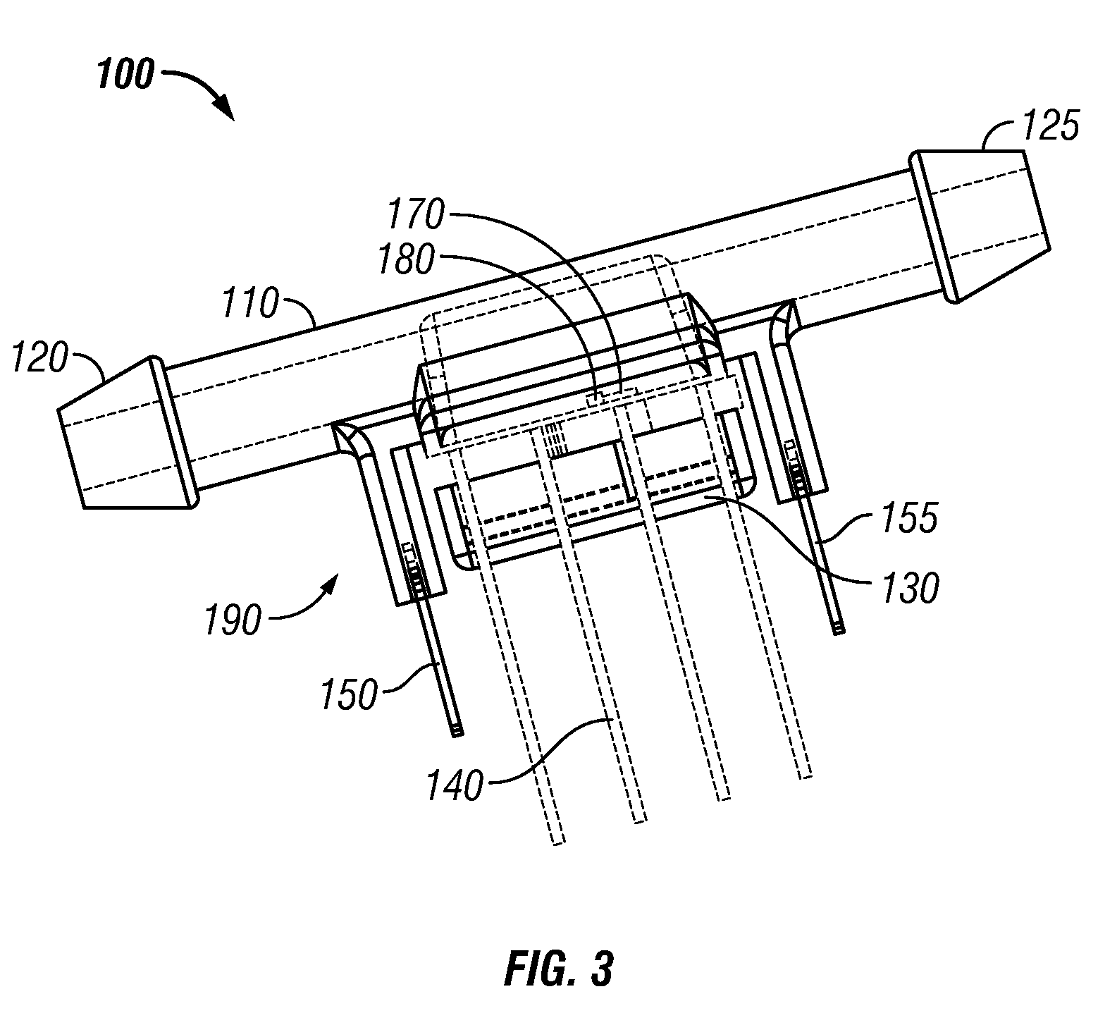
[0024]FIG. 1 illustrates a perspective view of a flow-through pressure sensor apparatus 100 utilizing surface mount technology (SMT), which can be implemented in accordance with a preferred embodiment. The apparatus 100 generally includes a housing 190 and a flow tube 110 having an inlet port 120 and an outlet port 125. A pressure sense die 180 and a programmable compensation integrated circuit 170 can be located on a substrate 130 and packaged inside the surface mount technology package housing 190, as shown in FIG. 3. The material of the substrate 130 can be configured from material such as, for example, ceramic, alumina, or a fiberglass PC board material, such as FR4 or FR5, although other ceramics may be utilized to implement substrate 130. Ceramic materials having a lower ...


PUM

PropertyMeasurementUnit
angleaaaaaaaaaa
angleaaaaaaaaaa
pressureaaaaaaaaaa

Abstract

A flow-through pressure sensor apparatus that reduces the dead space of a flow tube utilized to provide fluid communication between a pressure sense die and a fluid and with an absolute minimum trapped volume. A cover (e.g., plastic) with two-molded ports can be added to one side of the pressure sense die utilizing molded-in solder pins to improve ruggedness and rigidity. A temperature and a humidity sensor can also be mounted to a substrate (e.g., ceramic) in the flow path and can be connected to a programmable compensation integrated circuit on the opposite side utilizing a clip end of mounting pins or by vias through the substrate outside a pressurized area.

Description

TECHNICAL FIELD[0001]Embodiments are generally related to sensing devices and methods such as, for example, flow sensors, pressure sensors, humidity sensors, and temperature sensors. Embodiments are also related to flow-through pressure sensors.BACKGROUND OF THE INVENTION[0002]A number of processes and devices have been implemented to measure flow rate in different applications. Flow-through pressure sensors can be utilized in conjunction with an in-line orifice to measure very low flow rates and with reliable accuracy. Such pressure sensors have been utilized, for example, in various flow sensing devices such as medical applications, some of which utilize silicon piezoresistive sensing technology for measuring very low pressures. Other flow sensing implementations, for example, include environmental applications.[0003]The majority of flow-through pressure sensor configurations require some type of conduit so that a pressure-sensitive component can be disposed in fluid communication...

Claims


Application Information

Patent Timeline
Patent Type & Authority Patents(United States)
IPC IPC(8): G01L7/00
CPCG01L19/0023
Inventor BENTLEY, IANCOOK, JIMRICKS, LAMAR FLOYDBRADLEY, ALISTAIR DAVIDWADE, RICHARD
Owner HONEYWELL INT INC
Why Eureka
Try Eureka