Optical transceiver and projection covering member

a technology of optical transceivers and covering members, which is applied in the direction of optics, optical waveguide light guides, instruments, etc., can solve the problems of not providing an effect of attenuating the noise current (noise magnetic field) generated in the projection, electromagnetic waves may leak from a slight gap, and the electromagnetic wave absorber described in patent document 2 cannot provide a sufficient effect, so as to prevent a breakage of optical fibers

Active Publication Date: 2012-11-20
LUMENTUM JAPAN INC
View PDF9 Cites 3 Cited by
  • Summary
  • Abstract
  • Description
  • Claims
  • Application Information

AI Technical Summary

Benefits of technology

[0012]The present invention has been made in consideration of the above-mentioned conventional problems, and an object thereof is to provide an optical transceiver and a projection covering member that can suppress EMI noise radiated from a pigtail part.
[0014]In the present invention, the conductive elastic material for covering the projection contacts intimately the outer periphery of the opening part of the conductive case, and hence it is possible to shield the high-frequency electromagnetic wave radiated from the optical subassembly or the printed circuit board. In addition, the projection is covered with the conductive material having predetermined resistivity and contacts at least a part of the conductive material, and hence the noise current (noise magnetic field) itself generated in the projection can be attenuated by heat consumption. Therefore, according to the present invention, the EMI noise radiated from the pigtail part of the optical transceiver (part of the projection protruding from the case) can be suppressed.
[0021]According to the present invention, the conductive elastic material for covering the projection contacts intimately with the outer periphery of the opening part of the conductive case. Therefore, it is possible to shield the high-frequency electromagnetic wave radiated from the optical subassembly or the printed circuit board. In addition, the projection is covered with the conductive material having predetermined resistivity and contacts at least a part of the conductive material. Therefore, the noise current (noise magnetic field) itself generated in the projection can be attenuated by heat consumption. Thus, the EMI noise radiated from the pigtail part of the optical transceiver (the part of the projection protruding from the case) can be suppressed.
[0022]In addition, it is not necessary to cover the projection with a metal cap that contacts a lower case part and an upper case part or that is integral with the case. Therefore, a sufficient bending radius of an optical fiber can be maintained even if the optical fiber is pulled in a direction different from the insertion and withdrawal direction. Therefore, it is possible to prevent a breakage of the optical fiber at an optical fiber through-hole or in its vicinity, to prevent a breakage of a sheath of the optical fiber because of a contact between the optical fiber and the metal cap, and other problems. Further, a metal cap, that has a complicated shape and that needs a number of assembling steps, is not necessary, and hence it is also possible to prevent an increase in manufacturing cost.

Problems solved by technology

However, with respect to such a pigtail type optical transceiver, electromagnetic wave or noise current may occur in the printed circuit board or in the optical subassembly and may propagate through the projection protruding to the outside of the case so as to reach the outside of the case, which becomes a factor in generating the EMI.
However, the optical module described in Patent Document 1 only shields the EMI radiated from the protruding part of the projection covered with the elastic member on the outside thereof, but it cannot provide an effect of attenuating the noise current (noise magnetic field) generated in the projection.
Therefore, there is a problem that the electromagnetic wave may leak from a slight gap in the case.
In addition, the electromagnetic wave absorber described in Patent Document 2 cannot provide a sufficient effect of absorbing the electromagnetic wave of the EMI having a frequency of approximately several tens of GHz to 40 GHz generated by the optical subassembly.
In addition, there is a problem that the effect of suppressing the EMI generated by other components constituting the optical module is also insufficient.

Method used


Image

  • Optical transceiver and projection covering member
  • Optical transceiver and projection covering member
  • Optical transceiver and projection covering member

Examples


Embodiment Construction

[0031]Hereinafter, an embodiment of the present invention is described in detail with reference to the drawings.

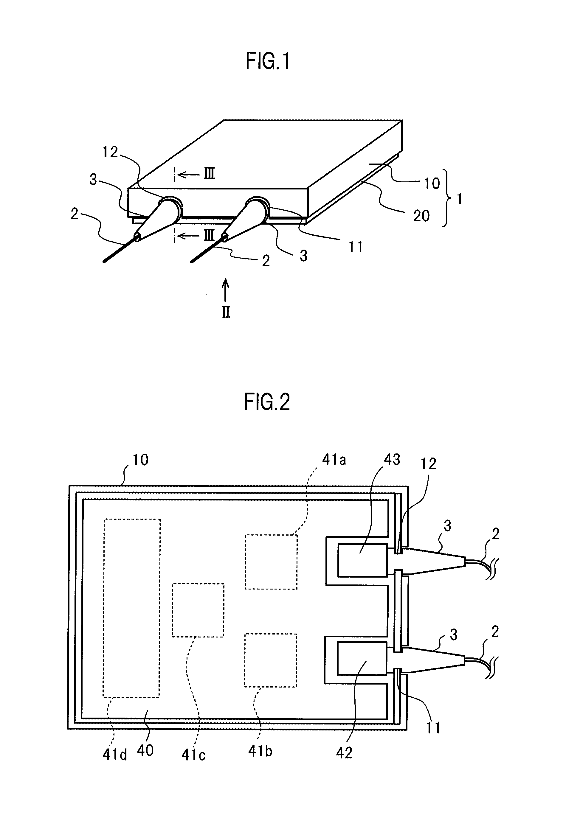
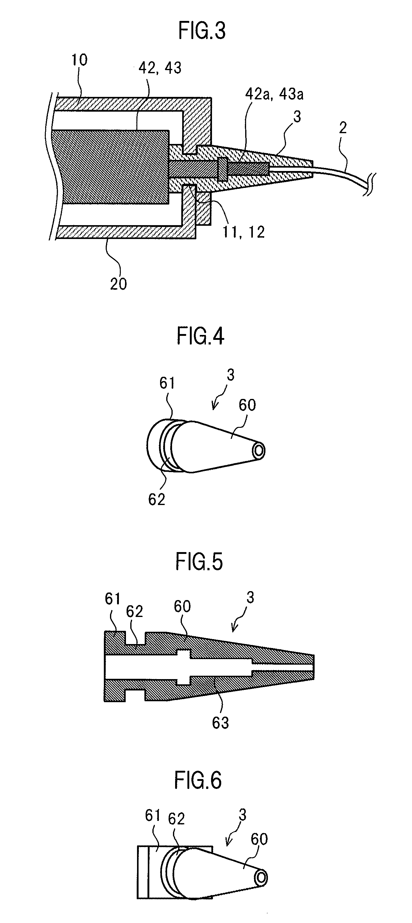
[0032]FIG. 1 is an upper perspective view of an optical transceiver according to an embodiment of the present invention. The optical transceiver according to this embodiment includes a case 1 made up of an upper case part (first case part) 10 and a lower case part (second case part) 20 that are made of conductive metal and are engaged with each other as illustrated in FIG. 1. The case 1 has opening parts 11 and 12 through which a projection which includes an optical coupler (that is described later) and an elastic covering member 3 pass from the inside to the outside of the case. An optical fiber 2 is externally inserted in the projection, and the elastic covering member 3 covers the projection so as to protect the projection.

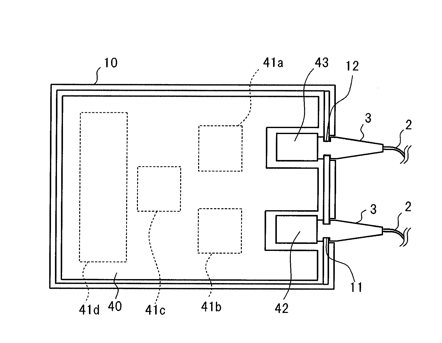
[0033]FIG. 2 is a view of the optical transceiver illustrated in FIG. 1 viewed in a direction of arrow II in the state in which the lower case part 2...


PUM


Abstract

An optical transceiver has a projection covering member that can suppress EMI noise radiated from a pig-tail part. An elastic covering member covers a projection which includes an optical coupler of an optical sub assembly. The covering member is made of a conductive elastic material having a predetermined resistivity. At least a part of an outer circumference surface of the elastic covering member comes into intimate contact with an outer periphery of a conductive opening part of a case for the optical transceiver while an inner circumference surface of the elastic covering member comes into intimate contact with the projection.

Description

CROSS-REFERENCE TO RELATED APPLICATION[0001]The present application claims priority from Japanese application JP 2008-108491 filed on Apr. 18, 2008, the content of which is hereby incorporated by reference into this application.BACKGROUND OF THE INVENTION[0002]1. Field of the Invention[0003]The present invention relates to an optical transceiver and a projection covering member. In particular, the present invention relates to a technique for suppressing electromagnetic interference (EMI).[0004]2. Description of the Related Art[0005]In recent years, the optical transmission speed of an optical transceiver has changed from 2.5 Gbit / s to 10 Gbit / s and further to 40 Gbit / s. Therefore, an internal clock frequency of a circuit used for optical communication or the like has also increased to be from several hundred MHz to several tens of GHz. In connection with that, the frequency of the EMI has also increased to be several tens of GHz. In particular, it is an urgent necessity to establish...

Claims


Application Information

Patent Timeline
Patent Type & Authority Patents(United States)
IPC IPC(8): G02B6/36
CPCG02B6/4246G02B6/4277G02B6/4292
Inventor MAEDA, FUMIHIDEKOGURE, TAICHI
Owner LUMENTUM JAPAN INC
Why Eureka
Try Eureka