Variable area nozzle assisted noise control of a gas turbine engine

a gas turbine engine and variable area technology, applied in the direction of machines/engines, liquid fuel engines, mechanical equipment, etc., can solve the problems of affecting the combination of tonal and broadband components and noise directivity, and achieve the effect of reducing the overall noise level of the engine, and reducing the noise of the engin

Active Publication Date: 2012-11-20
RTX CORP
View PDF7 Cites 1 Cited by
  • Summary
  • Abstract
  • Description
  • Claims
  • Application Information

AI Technical Summary

Benefits of technology

[0006]Noise from the engine includes a tonal component and a broadband component. When combined with other engine parameters, such as fan speed, modifying the effective nozzle exit area enables an operator to achieve similar thrust through the bypass flow path with different overall noise levels. Further, changing the effective nozzle exit area also alters the combination of tonal and broadband components and the noise directivity. Depending on a flight condition, such as approach, cruise, or take-off, the overall level of engine noise can be optimized, as well as the combinations of the tonal and the broadband components. Directivity of the engine noise can also be controlled.

Problems solved by technology

Further, changing the effective nozzle exit area also alters the combination of tonal and broadband components and the noise directivity.

Method used


Image

  • Variable area nozzle assisted noise control of a gas turbine engine
  • Variable area nozzle assisted noise control of a gas turbine engine
  • Variable area nozzle assisted noise control of a gas turbine engine

Examples


Embodiment Construction

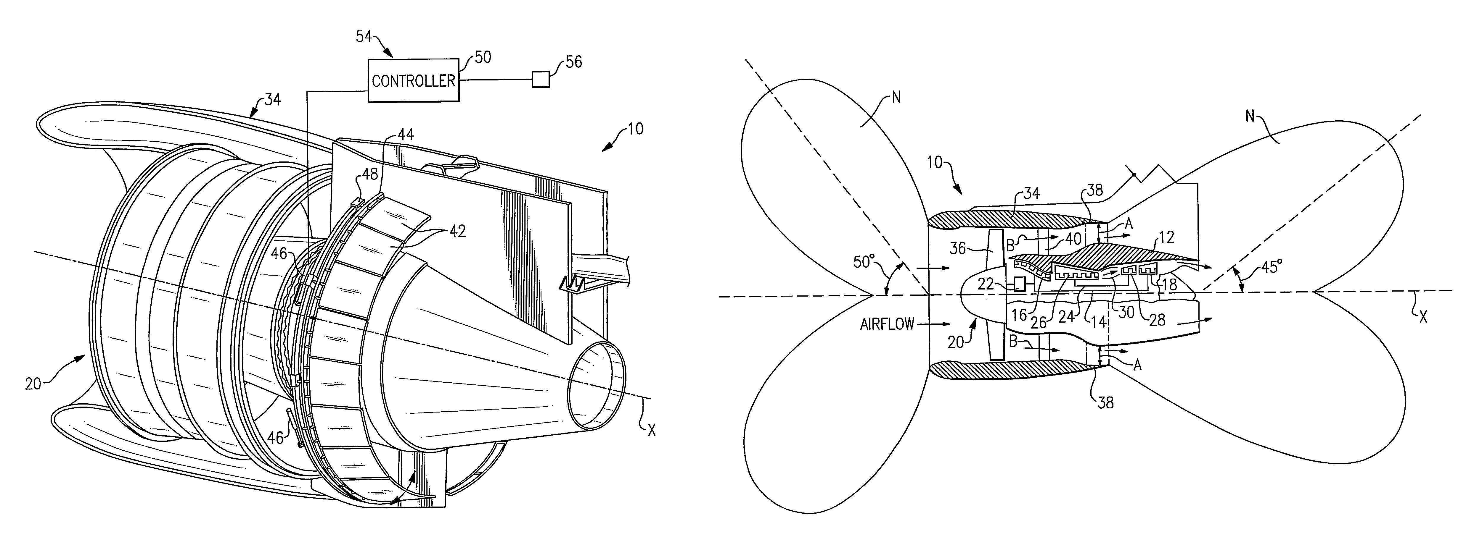
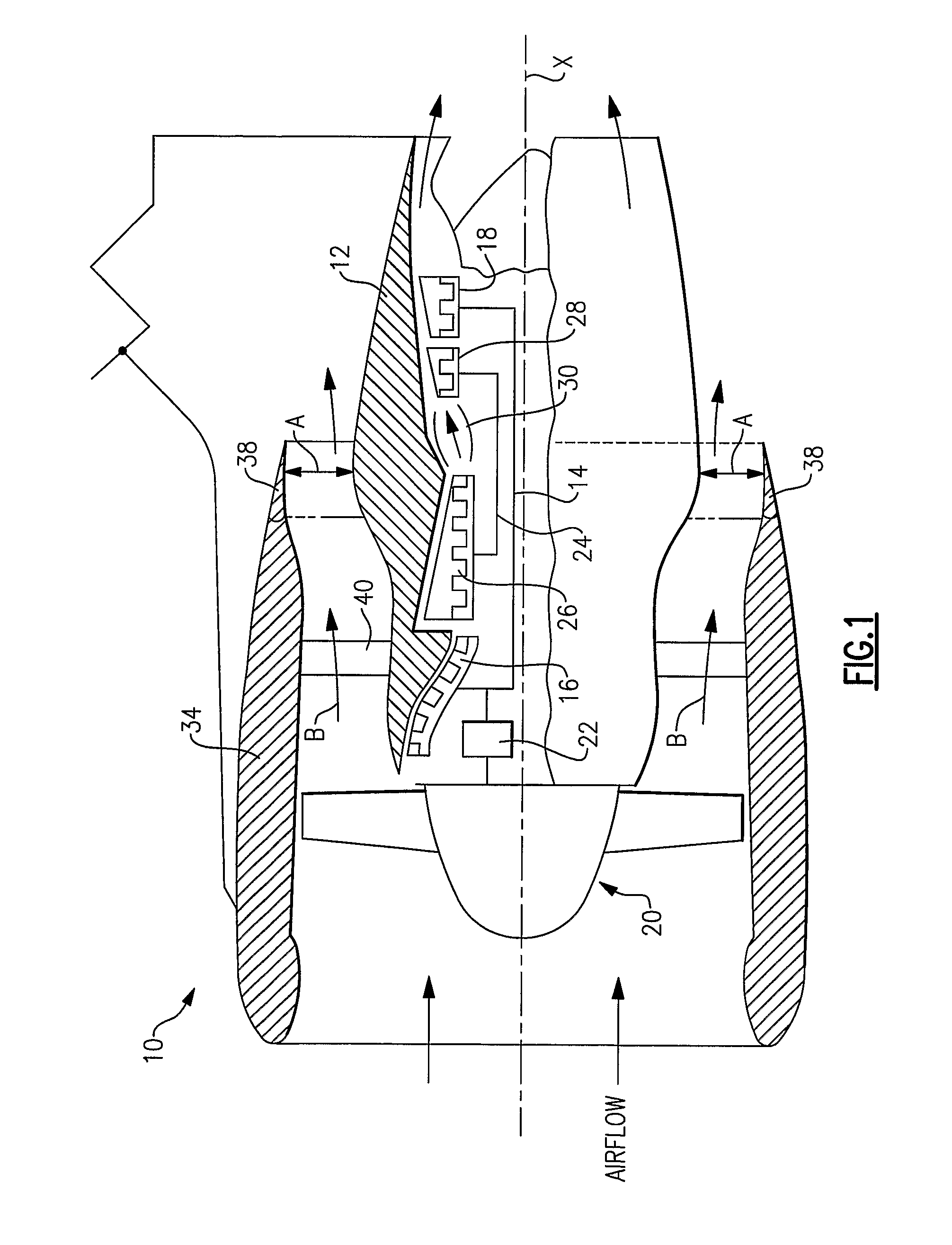
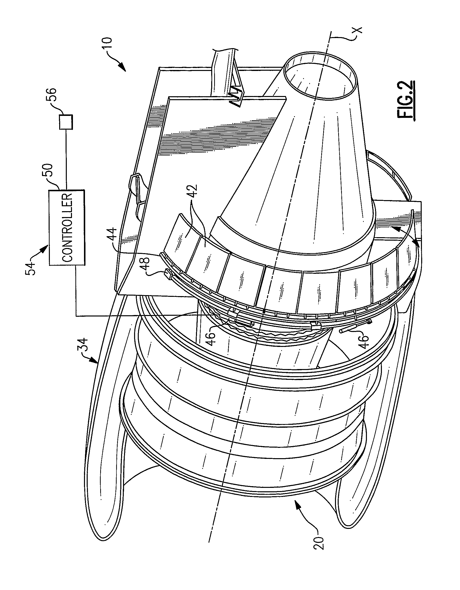
[0012]A geared turbofan engine 10 is shown in FIG. 1. The engine 10 includes a core nacelle 12 that houses a low rotor 14 and high rotor 24. The low rotor 14 supports a low pressure compressor 16 and low pressure turbine 18. In this example, the low rotor 14 drives a fan section 20 through a gear train 22. The fan section 20 rotates about an axis X and includes a plurality of fan blades 36. The high rotor 24 rotationally supports a high pressure compressor 26 and a high pressure turbine 28. A combustor 30 is arranged between the high pressure compressor 26 and high pressure turbine 28. The low and high rotors 14, 24 rotate about the axis X, and at least a portion of the core nacelle 12 is disposed within a fan nacelle 34. As is known, the engine 10 produces noise when running.

[0013]In the examples shown, the engine 10 is a high bypass turbofan arrangement. In one example, the bypass ratio is greater than 10:1, and the fan diameter is substantially larger than the diameter of the low...


PUM


Abstract

An example turbofan engine sound control system includes a core nacelle (12) housing a compressor and a turbine. The core nacelle is disposed within a fan nacelle (34). The fan nacelle includes a turbofan. A bypass flow path downstream from the turbofan is arranged between the two nacelles. A controller (50) is programmed to manipulate the nozzle exit area to control sound propagating from the engine. In one example, the controller manipulates the nozzle exit area using hinged flaps (42) to control engine sound. The hinged flaps open and close to adjust the nozzle exit area and the associated bypass flow rate.

Description

BACKGROUND OF THE INVENTION[0001]This invention relates to controlling noise propagating from a gas turbine engine, and, more particularly, to controlling noise by effectively altering the nozzle exit area.[0002]Gas turbine engines are widely known and used for power generation and vehicle (e.g., aircraft) propulsion. The engine produces engine noise due to the airflow moving through the engine and the various moving components within the engine. A person within the aircraft cabin may hear the engine noise. A person living near to an airport may often hear engine noise from the aircraft taking off and landing at the airport. Community noise is ordinarily defined as the aircraft noise perceivable by people located on the ground in the vicinity of the airport. Engine noise may limit an aircraft's ability to land at certain airports after certain hours, causing loss of revenue for an airline.[0003]Noise from the engine primarily propagates fore and aft of the engine. The frequency cont...

Claims


Application Information

Patent Timeline
Patent Type & Authority Patents(United States)
IPC IPC(8): F03D11/00F03B11/04F04D29/66F01D5/00F01D25/04
CPCF02K1/16F02K1/46F02K1/34F05D2260/96
Inventor LORD, WESLEY K.GRABOWSKI, ZBIGNIEW M.
Owner RTX CORP
Why Eureka
Try Eureka