Plasma processing apparatus

a processing apparatus and plasma technology, applied in the direction of accelerators, electric discharge tubes, light sources, etc., can solve the problems of satisfactory plasma level, achieve high uniformity, reduce the influence of fringe effects, and retain plasma axial symmetry at high levels

Active Publication Date: 2012-11-20
SAMCO
View PDF16 Cites 22 Cited by
  • Summary
  • Abstract
  • Description
  • Claims
  • Application Information

AI Technical Summary

Benefits of technology

[0026]The characteristic configuration of the coil in the plasma processing apparatus according to the present invention leads to the following effects.
[0027]Firstly, the rotationally symmetrical arrangement of a plurality of coil elements enables the entire coil to avoid the influence of a voltage drop and retain the axial symmetry of the plasma at high levels. Thus, the influence of the fringe effect is reduced. This means that it is possible to uniformly produce a large-diameter plasma. The resultant plasma will have particularly high uniformity in the circumferential direction.
[0028]Furthermore, in each coil element, the ground end is located under the feed end (i.e. closer to the object to be processed). This means that the ground end of the coil element intervenes between the plasma and the feed end of the coil. This is effective in impeding the sputtering of the dielectric body that insulates the coil from the plasma.

Problems solved by technology

Unfortunately, none of the induction coils of the plasma processing apparatuses that have been publicly recognized hitherto, including the ones disclosed in Patent Documents 1 and 2, cannot produce a plasma with a satisfactory level of uniformity; there is still room for improvement.

Method used


Image

  • Plasma processing apparatus
  • Plasma processing apparatus
  • Plasma processing apparatus

Examples


embodiment

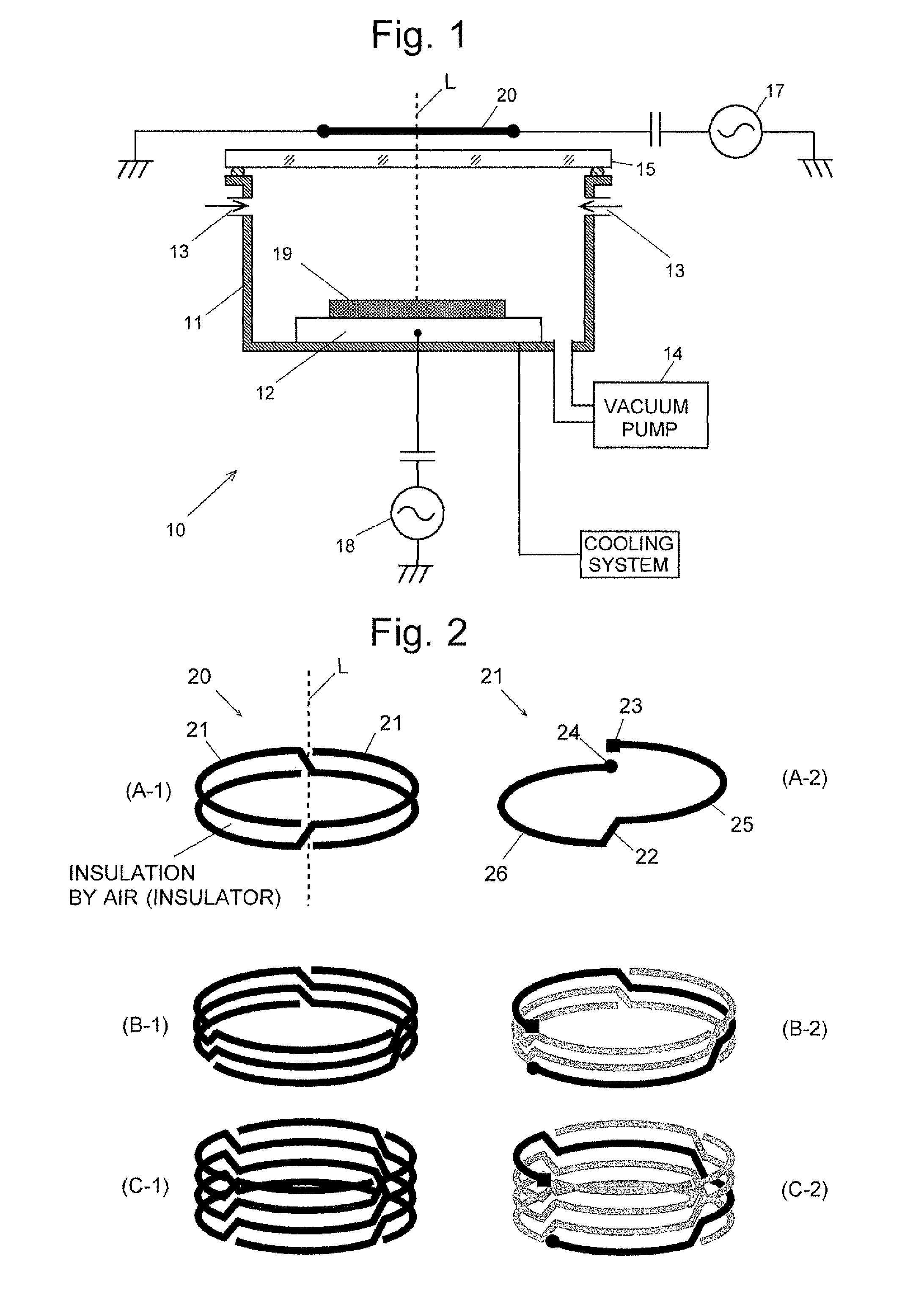
[0101]FIG. 6 is a schematic configuration diagram of an ICP etching apparatus 10 with an induction coil 30 according to the third mode mounted on a quartz plate 15. It should be noted that the gas inlets, vacuum pump, cooling system and other components are omitted from FIG. 6.

[0102]The induction coil 30 shown in FIG. 6 is structurally identical to that shown in FIG. 4; it consists of a first induction coil 31 composed of five coil elements 21 and a second induction coil 32 composed of three coil elements 21. The first and second induction coils 31 and 32 are mounted on the quartz plate 15 via spacers 34 so that their upper surfaces are level with each other.

[0103]The first and second induction coils 31 and 32 are arranged so that their common axis coincides with the central axis L of a silicon wafer as the object 19 to be processed, which is normal to the surface of the silicon wafer. The radii of the first and second induction coils 31 and 32 are 185 mm and 125 mm, respectively. E...

first modification

(First Modification)

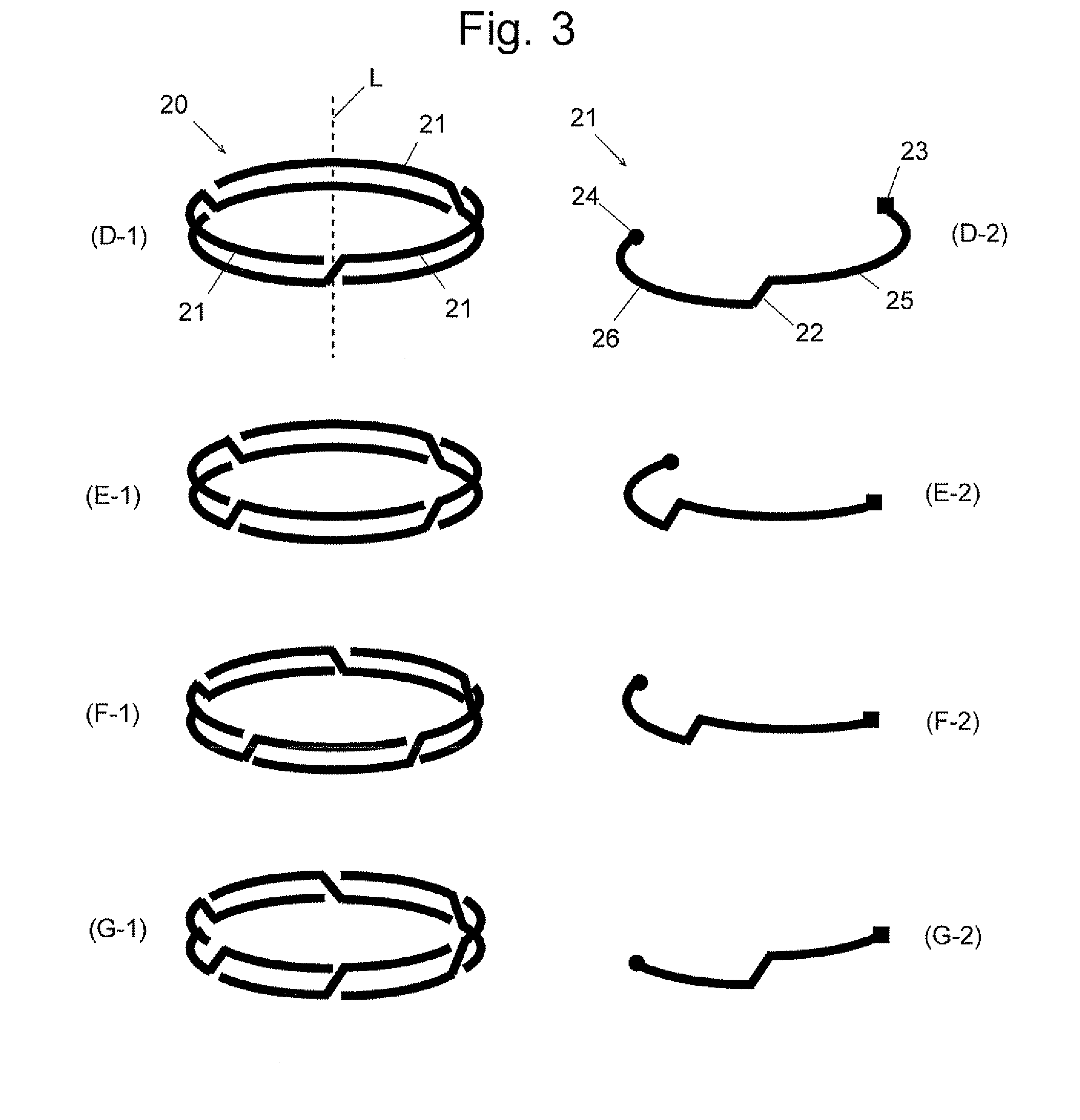
[0118]The width of the bottom portion 26 of the coil element 21 (i.e. the thickness in the axial direction) may be larger than that of the feed portion 25. FIG. 13 shows an example of such a coil element 21. This design further improves the plasma's uniformity and therefore allows the processing of samples having even larger diameters,

second modification

(Second Modification)

[0119]The bottom portion 26 of the coil element 21 may be comma-shaped. In this mode, the bottom portions 26 of the coil elements 21 should not overlap each other when the coil elements 21 are assembled.

[0120]FIG. 14 show two examples of the comma-shaped bottom portion 26. Specifically, FIG. 14(K) is a front view of the bottom portion 26 of the induction coil 20 consisting of two coil elements 21, and FIG. 14(K) is a front view of the bottom portion 26 of the induction coil 20 consisting of three coil elements 21.

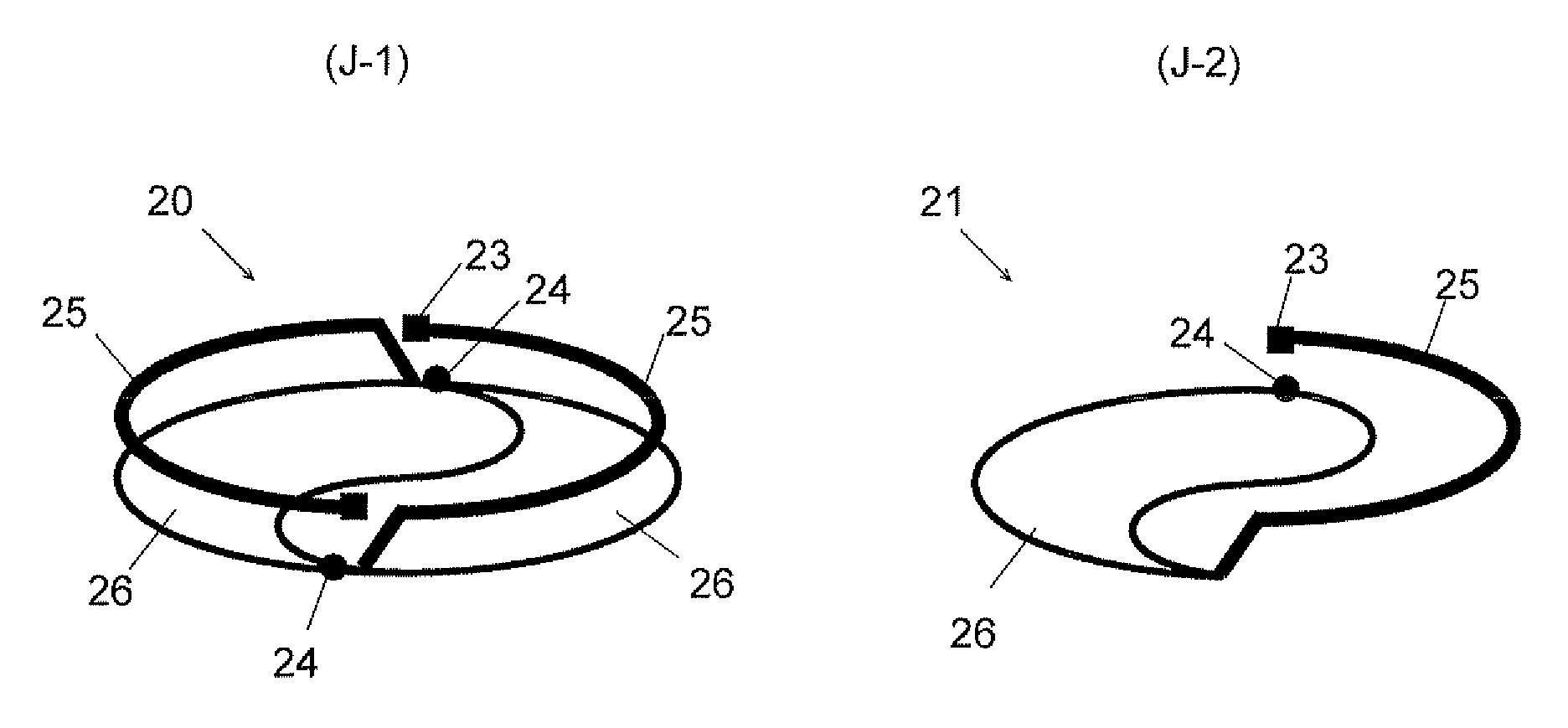
[0121]FIG. 15(J-1) is a schematic diagram of an induction coil 20 consisting of two coil elements 21 having a comma-shaped bottom portion 26. FIG. 15(J-2) is a schematic diagram of a single coil element 21 constituting the induction coil 20 shown in FIG. 15(J-1).

[0122]In the examples shown in FIGS. 14 and 15, the bottom surface is entirely covered by the bottom portions 26 when a plurality of coil elements are assembled. Alternatively, it is possible ad...


PUM


Abstract

An induction coil composed of n pieces of identically shaped coil elements (where n is equal to or greater than two), which are rotation-symmetrically arranged with respect to an axis normal to the surface of an object to be processed, is provided above the object, the coil elements being electrically connected in parallel. Each of the coil elements of the induction coil encircles the aforementioned axis, with the ground end and the feed end located at the same position on a projection plane on the object with the ground end under the feed end. Each coil element has a bottom portion shaped like an arc having a predetermined width and a central angle of 360° / n, with the ground end at one end thereof, and a feed portion shaped like an arc having a predetermined width, with the feed end at one end thereof, the feed portion being located above the bottom portion and electrically connected to the same bottom portion. It is also possible to assemble a plurality of coil elements so that the ground end of each coil element is located immediately below the feed end of another coil element.

Description

TECHNICAL FIELD[0001]The present invention relates to a plasma processing apparatus, such as a plasma etching apparatus, plasma enhanced CVD (chemical vapor deposition) apparatus or plasma cleaning apparatus.BACKGROUND ART[0002]In recent years, plasma processing technologies have been applied not only in the conventional fields of semiconductors but also a wider range of technical fields, including the fields relating to nanotechnologies, such as optical devices (e.g. semiconductor lasers or diodes), microelectromechanical systems (MEMS; e.g. gyroscopes or sensors) and carbon nanotubes, as well as medical and biotechnological applications (e.g. micro knives or sterilization).[0003]The expansion of the application fields has also been accompanied by a growing demand for higher productivity, which has naturally led to a request for improving the efficiency of the plasma processing apparatus. The efficiency can be improved in several ways, e.g. by increasing the size of the sample (sub...

Claims


Application Information

Patent Timeline
Patent Type & Authority Patents(United States)
IPC IPC(8): H05B31/26
CPCH01J37/32174H01J37/321
Inventor NAKAGAMI, SHINJINAKANO, HIROHIKO
Owner SAMCO
Why Eureka
Try Eureka