Thermal head and printer

a printer and thermal head technology, applied in printing and other directions, can solve the problems of increasing the number of manufacturing steps, increasing the manufacturing cost, and insufficient heat transfer from the heating portions to the thermal recording medium, and achieves high heating efficiency, good contact, and high efficiency

Inactive Publication Date: 2012-11-20
SEIKO INSTR INC
View PDF8 Cites 0 Cited by
  • Summary
  • Abstract
  • Description
  • Claims
  • Application Information

AI Technical Summary

Benefits of technology

[0005]The present invention has been made in view of the above-mentioned circumstances, and it is an object of the present invention to provide a thermal head capable of making good contact to a thermal recording medium or the like to increase heat transfer efficiency while maintaining the number of manufacturing steps and manufacturing cost, and also to provide a printer including the thermal head.

Problems solved by technology

If there is such a hollow, the hollow forms a space when the thermal recording medium and the surface of the abrasion-resistant layer are brought into contact with each other for printing, resulting in insufficient transfer of heat from the heating portions to the thermal recording medium.
Accordingly, there is an inconvenience that the number of manufacturing steps is increased to raise manufacturing cost.

Method used


Image

  • Thermal head and printer
  • Thermal head and printer
  • Thermal head and printer

Examples


Embodiment Construction

[0035]Now, a thermal head and a thermal printer (printer) according to an embodiment of the present invention are described below with reference to the accompanying drawings.

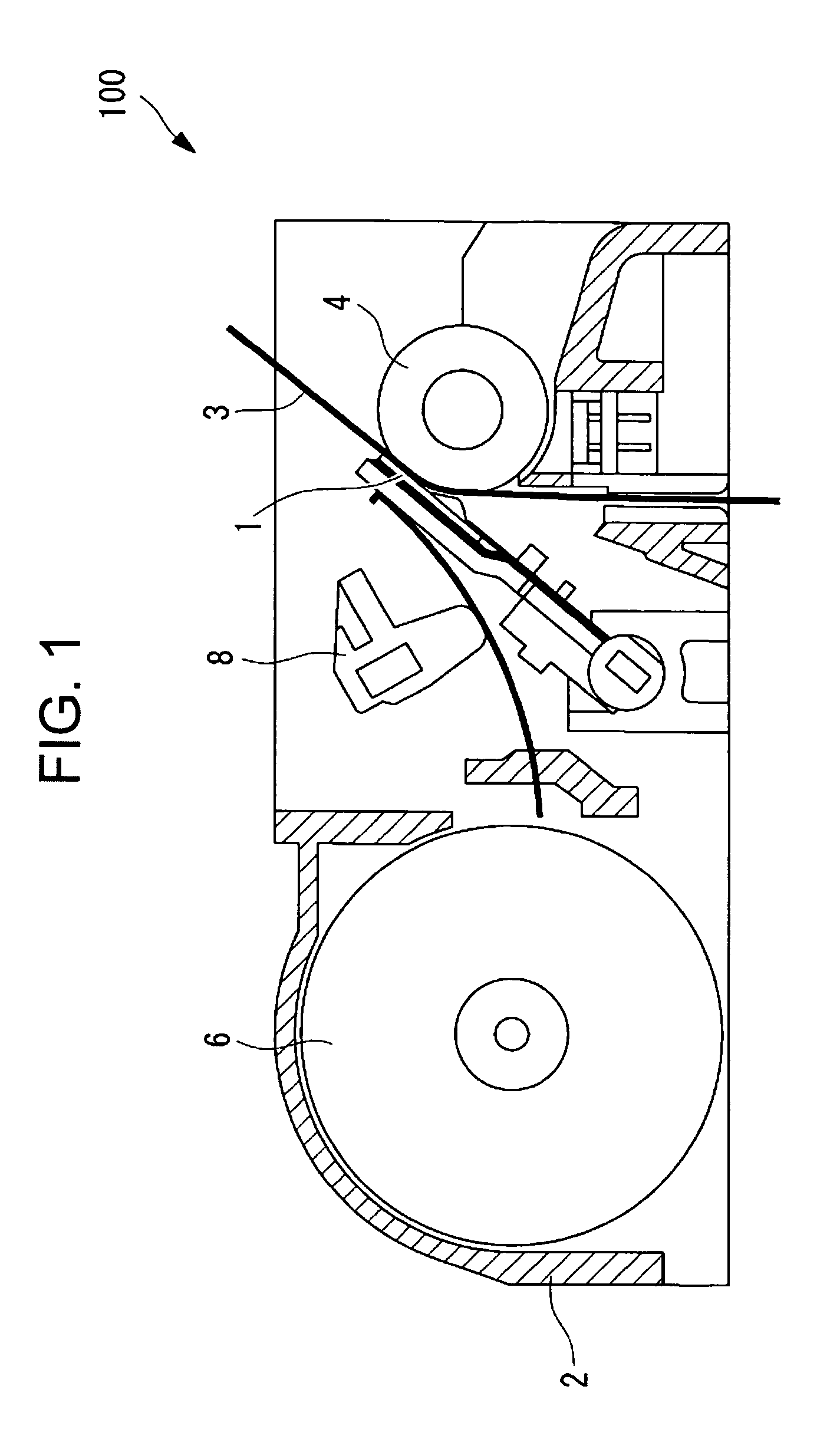
[0036]A thermal head 1 according to this embodiment is used for, for example, a thermal printer 100 as illustrated in FIG. 1. The thermal printer 100 includes a main body frame 2, a platen roller 4 disposed horizontally, the thermal head 1 disposed so as to be opposed to an outer peripheral surface of the platen roller 4, a paper feeding mechanism 6 for feeding an object to be printed, such as thermal paper (thermal recording medium) 3, between the platen roller 4 and the thermal head 1, and a pressure mechanism 8 for pressing the thermal head 1 against the thermal paper 3 with a predetermined pressing force.

[0037]Against the platen roller 4, the thermal head 1 and the thermal paper 3 are pressed by the operation of the pressure mechanism 8. Accordingly, a load of the platen roller 4 is applied to the thermal he...


PUM


Abstract

Provided is a thermal head capable of making good contact to a thermal recording medium or the like to increase heat transfer efficiency while maintaining the number of manufacturing steps and manufacturing cost. Provided is a thermal head (1) including: a flat plate-shaped substrate main body (13); a heating resistor (15) of a substantially rectangular shape formed on a surface of the flat plate-shaped substrate main body (13); and a pair of electrodes (17A, 17B) connected to both ends of the heating resistor (15), for supplying power to the heating resistor (15), in which the pair of electrodes (17A, 17B) respectively include connecting portions (27A, 27B) having a width dimension smaller than a width dimension of the heating resistor (15), and the connecting portions (27A, 27B) are connected to the heating resistor (15) at positions shifted from each other in a width direction of the heating resistor (15).

Description

FIELD OF THE INVENTION[0001]The present invention relates to a thermal head and a printer.DESCRIPTION OF THE RELATED ART[0002]There has been conventionally known a thermal head for use in thermal printers that are installed in compact information equipment terminals typified by a compact hand-held terminal, which is capable of printing on a thermal recording medium by selectively supplying a plurality of heating resistors with current and pressing the surface of an abrasion-resistant layer covering heating portions of the heating resistors against the thermal recording medium (see, for example, Japanese Patent Application Laid-open No. Hei 04-319446).[0003]In such a thermal head, steps are defined between the heating portion of the heating resistor and each of a pair of electrodes connected to both end portions of the heating resistor. Because of the steps, a hollow is formed in the surface of the abrasion-resistant layer covering the heating portions. If there is such a hollow, the...

Claims


Application Information

Patent Timeline
Patent Type & Authority Patents(United States)
IPC IPC(8): B41J2/335
CPCB41J2/3351B41J2/33545
Inventor SHOJI, NORIYOSHISANBONGI, NORIMITSUMOROOKA, TOSHIMITSUKOROISHI, KEITARO
Owner SEIKO INSTR INC
Why Eureka
Try Eureka