Method for operating C-arm systems during repeated angiographic medical procedures

a c-arm system and angiography technology, applied in the field of clinical xray angiography, can solve the problems of long procedure time, difficult 2d angiographic image generation, and failure to produce a 2d image, etc., and achieve the effect of easy and fast acquisition

Active Publication Date: 2012-11-20
SIEMENS HEALTHCARE GMBH
View PDF0 Cites 16 Cited by
  • Summary
  • Abstract
  • Description
  • Claims
  • Application Information

AI Technical Summary

Benefits of technology

[0012]The driving step may be performed automatically or manually. In the latter case, the driving may be performed manually using visual cues indicating the direction and magnitude of necessary movements by the C-arm and the radiographic table. The method may also comprise the additional step of generating a joint visualization of the target and source images. The joint visualization may be accomplished by displaying a side-by-side comparison of the source and target images; displaying an overlay of fused source and target images; or displaying a composite image resulting from a subtraction of the two images that allows the easy detection of small differences between the two images.

Problems solved by technology

However, the generation of a 2D angiographic image that matches or closely matches another acquired at a previous time for these comparisons is often challenging.
This subjects the patient to an additional dosage of X-rays, an additional dosage of contrast, and lengthens the procedure time.
Since this approach depends on visual comparisons and manually-driven movements of components of the C-arm system, it is tedious and it often fails to produce a 2D image that accurately matches another acquired at a previous time point.
Secondly, the patient's position on the radiographic table may be different between the initial angiogram and the second angiogram due to the acquisition of the two images on different days, or due to a patient's motion in between the two imaging times. The trouble in producing a 2D image that accurately matches a previously-acquired image may lead to the difficulty in assessing disease progression or the efficacy of treatment, since the two images being compared do not lend themselves to a point-to-point comparison.

Method used


Image

  • Method for operating C-arm systems during repeated angiographic medical procedures
  • Method for operating C-arm systems during repeated angiographic medical procedures
  • Method for operating C-arm systems during repeated angiographic medical procedures

Examples


Embodiment Construction

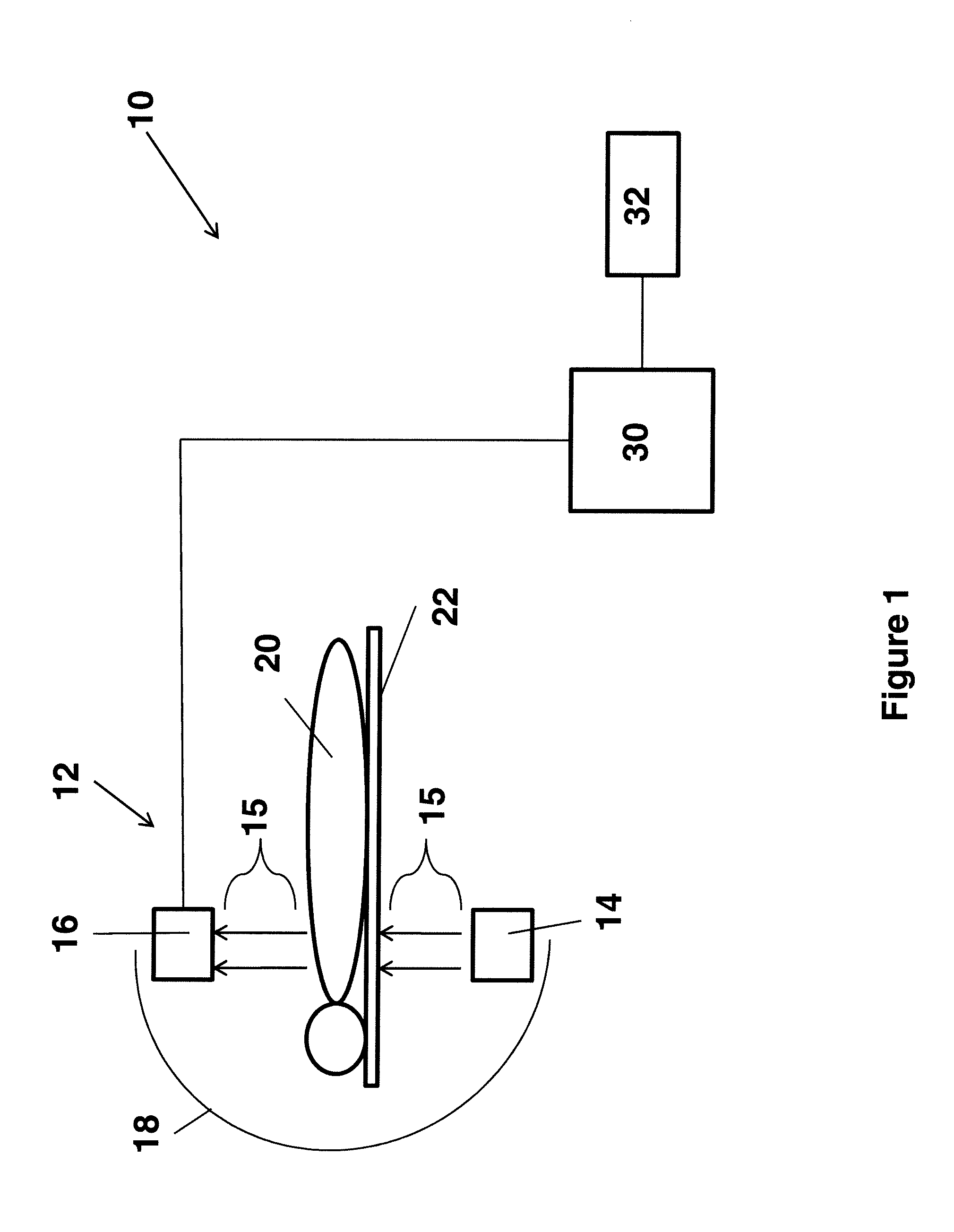
[0023]FIG. 1 is a block diagram of an X-ray C-arm imaging system 10 (simplified) that operates in accordance with the present invention. The system 10 comprises a rotational X-ray imaging apparatus 12 having an X-ray source 14 that generates X-ray beams 15 towards an X-ray detector 16. The X-ray source 14 and the X-ray detector 16 are mounted on opposite ends of, and coupled to one another via, a rotatable C-arm gantry arrangement 18. A patient to be imaged 20 is positioned on a radiographic support table 22 between the two components 14, 16 such that the X-ray beams 15 pass through the patient 20, and in particular, the anatomical area of interest, and project onto the X-ray detector 16. The detector 16 converts the raw X-ray projections into image data signals for subsequent processing by the C-arm system 10. As a result of the rotation of the C-arm 18, the X-ray source 14 and the X-ray detector 16 are moved about the patient 20 and the table 22 in a coordinated manner so that the...


PUM

PropertyMeasurementUnit
imaging timeaaaaaaaaaa
distancesaaaaaaaaaa
volumeaaaaaaaaaa

Abstract

A method (100) for positioning and operating components (18, 22) of an X-ray C-arm system (10) during repeated angiographic medical procedures.

Description

CROSS-REFERENCE TO RELATED APPLICATIONS[0001]This application claims the benefit of Provisional U.S. Patent Application Ser. No. 61 / 255,543, entitled, “Method for Positioning of C-arm Systems during Repeated Angiographic Medical Procedures”, filed in the name of Ashraf Mohamed on Oct. 28, 2009, the disclosure of which is also hereby incorporated herein by reference.FIELD OF INVENTION[0002]This invention relates to clinical X-ray angiography and, in particular, the acquisition of repeated or follow-up angiograms to, for example, assess the efficacy of treatment, or progression of a disease.BACKGROUND OF THE INVENTION[0003]An X-ray C-arm system is X-ray imaging apparatus that is used by healthcare professionals to obtain real-time images of internal structures of a patient, such as the vasculature. The imaging apparatus may be a rotational X-ray imaging device that acquires a series of 2D X-ray projections of the anatomical region of interest along an arced path. The type and configur...

Claims


Application Information

Patent Timeline
Patent Type & Authority Patents(United States)
IPC IPC(8): G01N23/04
CPCG06T11/005A61B6/4441A61B6/504A61B6/5235G06T2211/404
Inventor MOHAMED, ASHRAF
Owner SIEMENS HEALTHCARE GMBH
Why Eureka
Try Eureka