Component holding device
a technology of holding device and component, which is applied in the direction of screw, threaded fastener, container discharging method, etc., can solve the problem of limited gas discharge to the outside air, and achieve the effect of effectively preventing gas leakag
- Summary
- Abstract
- Description
- Claims
- Application Information
AI Technical Summary
Benefits of technology
Problems solved by technology
Method used
Image

Examples
first embodiment
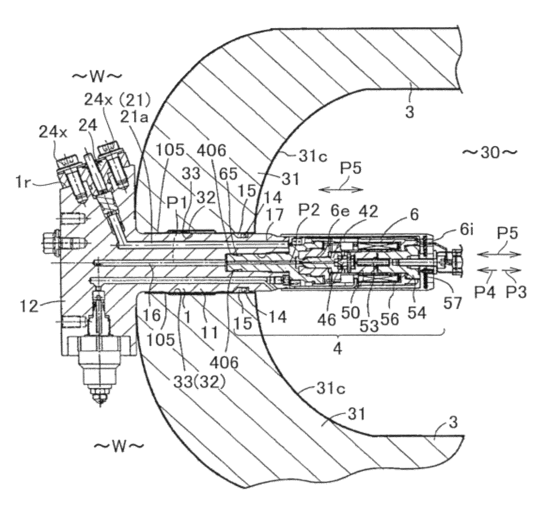
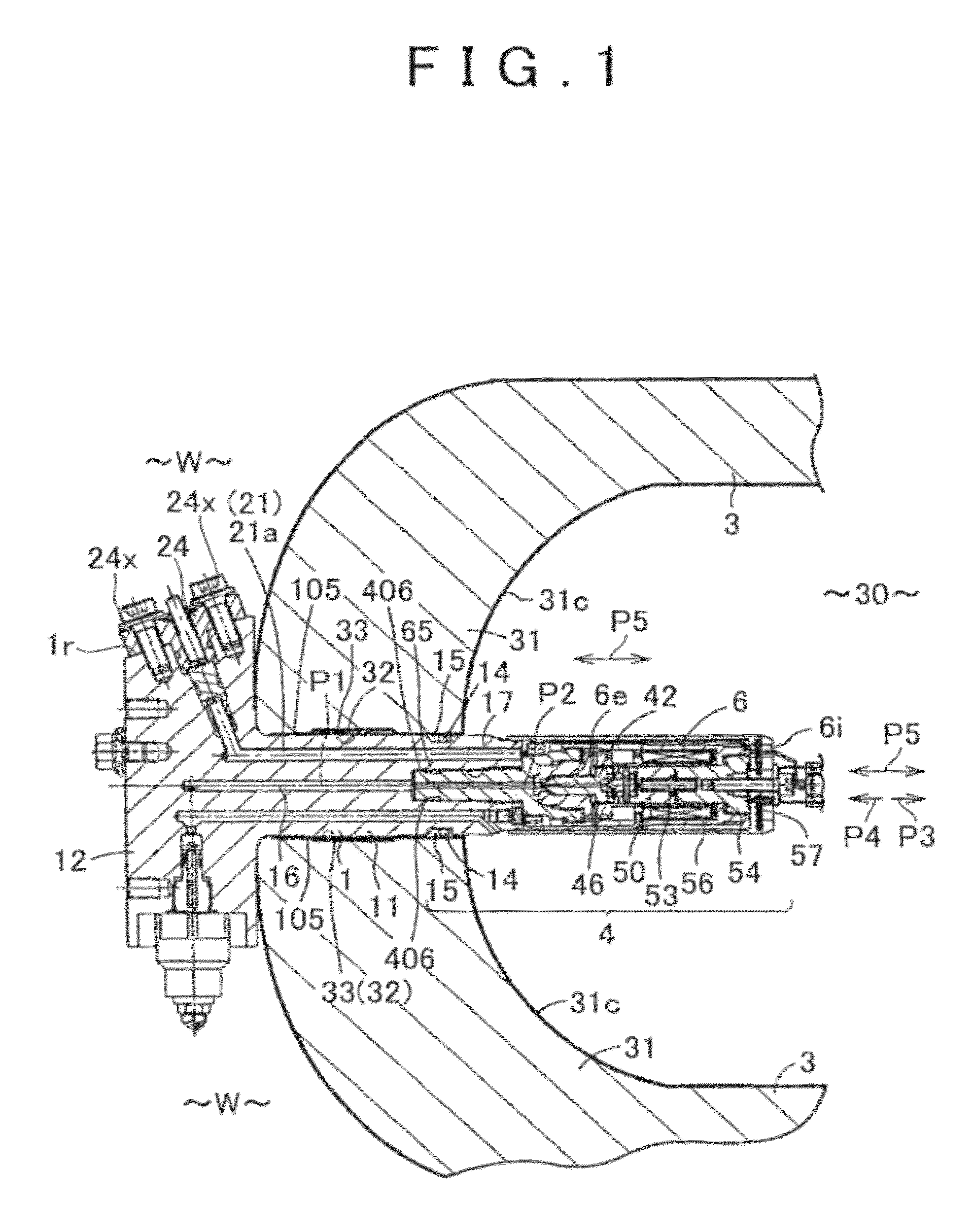
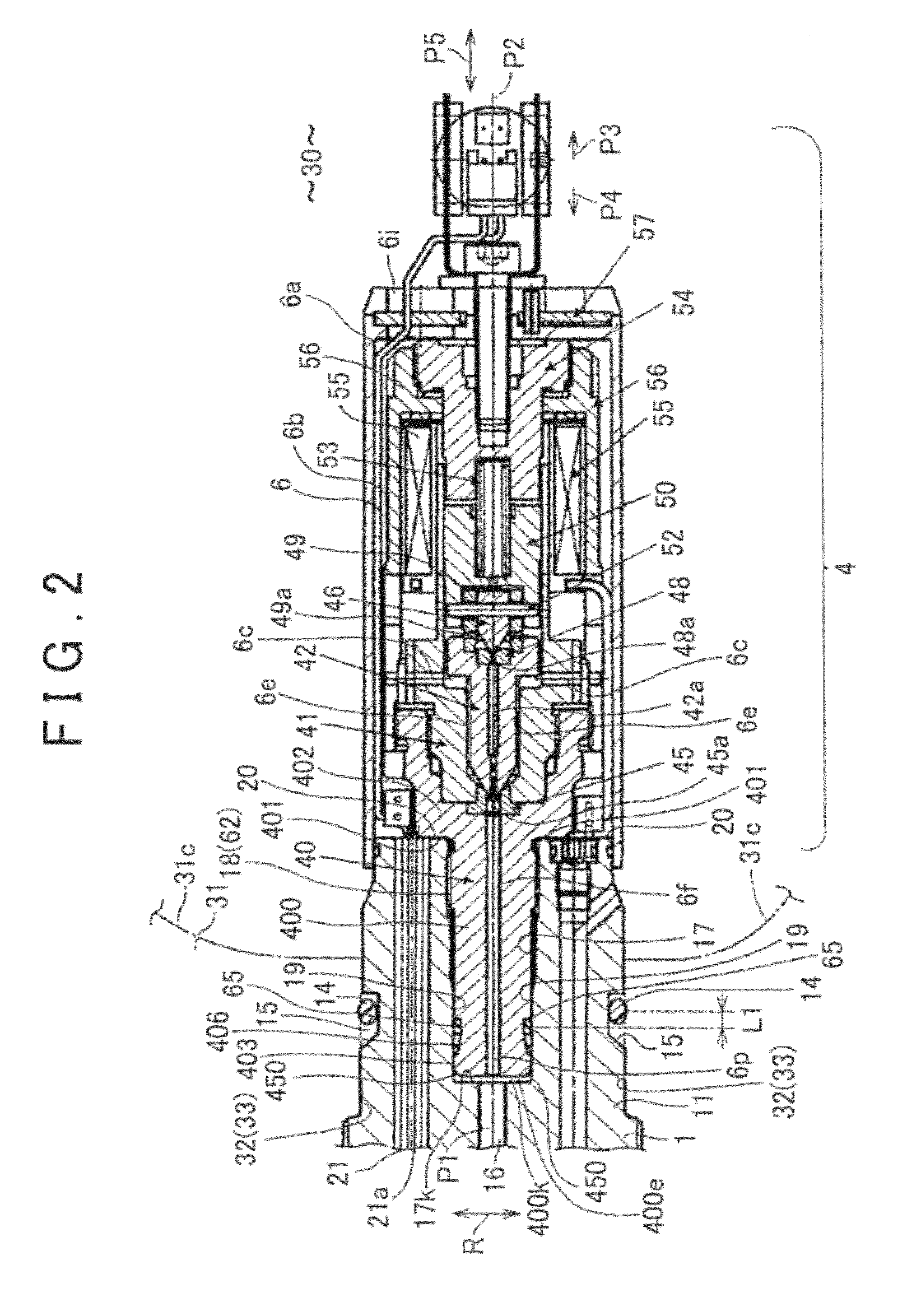
[0032](First Embodiment) the present invention will be described with reference to FIG. 1 to FIG. 6. The first embodiment is applied to a fuel cell system used in a vehicle, electrical apparatus, electronic apparatus, stationary equipment, transportable equipment, etc. Overall configuration is described first. As shown in FIG. 1 and FIG. 2, a fluid supply valve assembly device has a fixing member 1 and a fluid supply valve 4 (electrical apparatus) that is removably mounted to the fixing member 1. Overall configuration is described first.
[0033]As shown in FIG. 1, the fixing member 1 is mounted to a mounting hole 32 in a tank wall 31 with an inner surface 31c that forms a tank chamber 30 (fluid tank chamber, source of intruding gas) of a tank 3 that stores gas (hydrogen gas) at high pressure. High pressure gas (hydrogen gas) is stored in the tank chamber 30. The pressure in the tank chamber 30 is higher than atmospheric pressure and generally maintained within a range of 10 to 250 MPa...
second embodiment
[0064](Second Embodiment) FIG. 7 illustrates a This embodiment basically possesses the same configuration and effects as the first embodiment. Thus, a description is now made with its focus on the differences. As shown in FIG. 7, the other end 87f of the vent path 87 is formed in the downwardly oriented surface 24w of the plug 24. Furthermore, in order to prevent water such as rainwater existing in the outside air W from directly contacting the resistance member 9, a protective cover 95 as a protective member that protects the resistance member 9 is fixed to the plug 24 with a fastener 95x. Since the direct contact of water such as rainwater to the resistance member 9 is avoided, a longer operating life of the resistance member 9 can be achieved.
[0065](Third Embodiment) FIG. 8 illustrates a third embodiment. This embodiment basically possesses the same configuration and effects as the second embodiment. Thus, a description is now made with its focus on the differences. As shown in ...
fourth embodiment
[0066](Fourth Embodiment) FIG. 9 illustrates a This embodiment basically possesses the same configuration and effects as the second embodiment. Thus, a description is now made with its focus on the differences. As shown in FIG. 9, the end surface 1r of the fixing member 1 is provided with a plurality of internal thread holes 1m that are opened to the end surface 1r. An external thread of each of plural fastening bolts 24x is inserted in an insertion hole 24e formed in the flange 24c of the plug 24, and then screwed into the internal thread of the respective internal thread holes 1m. Accordingly, the plug 24 (wire holding section) is removably fixed to the fixing member 1 while inserted in the first hole 21. The one end 87e of the vent path 87D is communicated with the gas residual section 28. The other end 87f of the vent path 87D is communicated with the internal thread hole 1m. Micro clearance is formed between the external thread of the fastening bolt 24 and the internal thread ...
PUM
 Abstract
Description
Claims
Application Information
 - R&D Engineer
- R&D Manager
- IP Professional
- Industry Leading Data Capabilities
- Powerful AI technology
- Patent DNA Extraction
Browse by: Latest US Patents, China's latest patents, Technical Efficacy Thesaurus, Application Domain, Technology Topic.
© 2024 PatSnap. All rights reserved.Legal|Privacy policy|Modern Slavery Act Transparency Statement|Sitemap